(EDIT: I have found out that this kind of equipment is usually called “body rollers”, or an “auto rotisserie”, – and quite often provides another crucial degree of rotational freedom, like this one. That’s my first search hit, just an example, I’m unaffiliated.)
Making one piece of custom supplementary hardware is never enough. I was talked into building this one, too, and it’s proven to be extremely useful.
Note that this is not a step-by-step how-to on building a push frame for your own MB 207D (or 307D, or any other). It’s more a description of the thinking and manufacturing process, with a few pitfalls mentioned. Same principles can be used for other vehicles. There are certainly other ways of achieving the same, better or worse.
And I can’t be held responsible if a ton of steel crushes someone because of something read online. Duh!
Grand plan
The issue is as follows: I need to move the van body. Sideways. Then turn it around 180° in a 6x6 meter area. Over and over again.
We first thought putting frames under each wheel, but decided against it for two reasons. First, I wouldn’t be able to remove neither the van’s wheels, nor the axles. Second, the small frame wheels, 16 of them, would cost too much. No, really. Their price is not proportional to size.
We reckoned there’s another approach: a frame for the entire body. It goes like this.
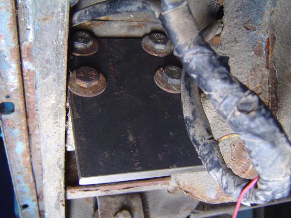
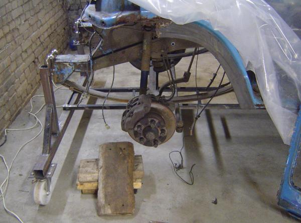
At the front, the radiator is mounted on a cross bar, which is attached to the chassis by eight M10 bolts. I have already removed the entire engine, so anything can be mounted using these screw holes. But here’s a picture from a long time ago, so you can understand what I’m writing about.
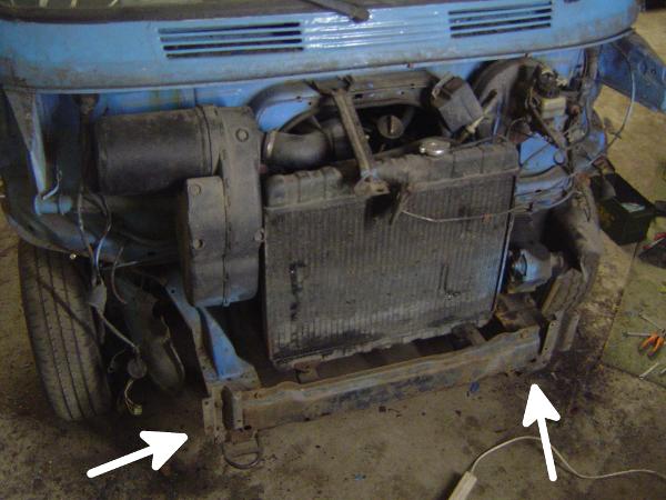
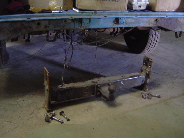
At the back, the tow bar can be removed, giving another eight holes, also M10.
Therefore, there are four stable mount points, where plates can be attached to the chassis. Weld four vertical “legs” to these plates – two at the front, two at the back. Weld these legs to cross bars with wheels at both ends. You’ve got yourself a minimal frame.
I started off by mocking up a drawing, then taking measurements. I kept revising as I progressed, and here’s the final version (rear at the top, front at the bottom, dimensions not to scale):
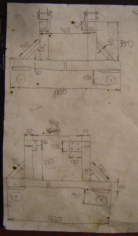
Notice there’s a few dimensions missing – most importantly, everything around the mount points. I’ve written them down on the plates themselves and forgot to put them in the drawing. Anyway, the spacing between bolts’ center-points are: 97x82 mm at the front, 69x46 mm at the back. Don’t trust me on this one, though, I’m from the Internet.
The spacing for wheel mount plates depends solely on the wheels you’ve got.
Attaching the frame to the chassis
I first manufactured these 4 plates. They’re made out of a steel strip 8 mm thick, 100 mm wide, 180/140 mm long for the front/back respectively. Nothing too precise here. What has to be precise is where you drill the holes. I went and checked immediately after.
The bolts are 30 mm long, but that’s not critical. They can be unnecessarily long and give one a pain in the ass when tightening the nuts, if such is the desired effect.
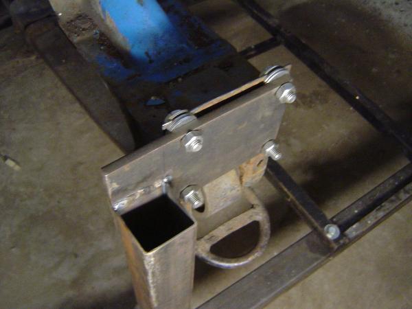
Here the bolts should be at least 80 mm long (not counting the head, of course). Note that there’s only about 5 cm of space on the other side, so the bolts can’t be inserted the other way around.
Wheel assembly
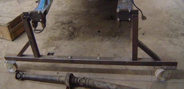
I then built two lower cross bars that the wheels attach to.
As mentioned, this depends mainly on the wheels on hand. I had four big ones, the specs say they can hold up to 500 kg each. The van’s body weighs about 500-700 kg, plus 100-200 kg for each axle – a total of 700-1100 kg, unevenly distributed.
We decided it would hold.
For the cross bar, I used 60x60x4 mm square pipe, because it felt solid enough. The van is about 1820 mm wide, so I cut my two pipe segments to that length, then cut two pieces of 40x6 mm strip for each wheel (a total of 8 strips).
40x4 mm would have worked just as well – the cross bar is 4 mm thick, after all, and if something broke under the weight, it would be the cross bar. But pwf, who went to the metal depot, wanted to prove they’ve got stuff that’s not available if you’re ordering online. So 40x6 mm it is.
Anyway, here’s a bottom view of the wheel mount. It’s pre-drilled and TIG-welded for alignment.
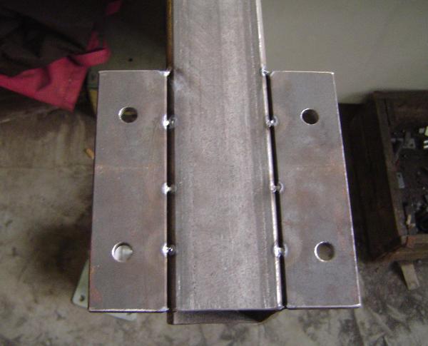
In cases like this, I would now rather weld it on with the wheels attached – less toying around with precise positioning.
Here’s the wheel assembly.
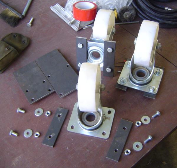
From 10 o’clock, clockwise: mount plates, rear and front; assembled wheel mounts, top and bottom views; disassembled wheel mount, exploded view.
Notice that the holes I drilled are not center-aligned. This, again, is solely due to the wheels I’m using.
To make these strips identical, I first drilled 4 mm center-holes in one piece, then used it as a template for the rest. This is standard practice. If the template is screwed, then everything is screwed, then I am screwed. So I was vewy-vewy-caweful.
After TIG-welding the strips to the cross bar, I stick-welded them, since this is faster and cheaper.
Legs
At this point, I had two fully assembled cross bars with wheels. Really dangerous to ride around the workshop.
I could measure their height, and how much the chassis mount plates protruded, so I could now decide how long my legs should be.
I jacked the van up and did that, then cut appropriate lengths off a 50x50x2 mm square pipe. This can be a lot thinner than the cross bar, since the main force applied is compression, not bending. Also, we had that as a leftover. And it doesn’t weigh too much, which at this point was starting to become an issue.
I also put in square pipes diagonally, to prevent the legs breaking off sideways.
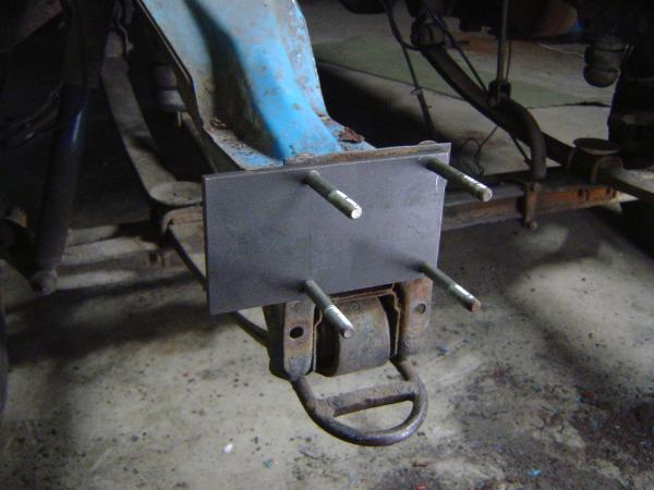
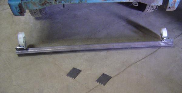
Long story short, here’s how it looked at the back before I screwed it to the chassis.
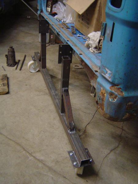
I don’t particularly like how the legs are welded to the mount plates. I’d now rather have spent a lot of time cutting away slots, so one inserts into the other. Too late, Captain Hindsight.
Final touches
At the front, I had to put in some spacers for better vertical alignment.
At the back, it fit as planned.
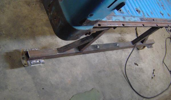
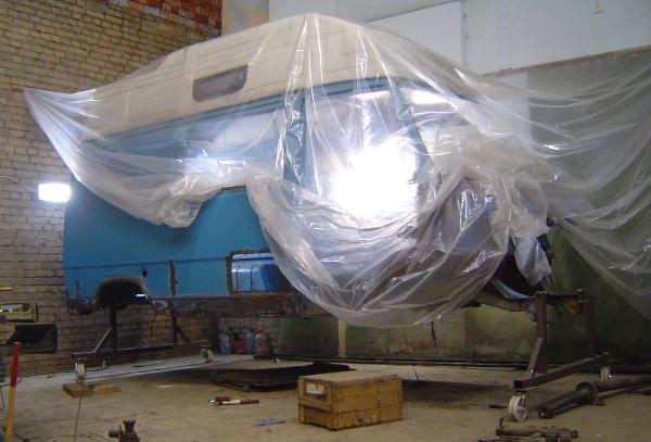
The whole thing didn’t feel stable enough when I tried to push the van, so I screwed a segment of metal stairs to both parts of the frame lengthhwise, underneath the van. Call it a spine. You can see a part of it in the picture below.
The spine is removable and can be attached whether or not the axles are still in place. When I was sure the whole thing wouldn’t collapse, I removed the axles.
One day, I will gimp the frame out, and the van will levitate.