I’ll document the developments that happened since the previous post, mainly for historical purposes.
Power safety during prototyping
The power connector (screw terminals) on the slave board weren’t sturdy enough and would jiggle if wiggled. Then the prototype board got burned – for a whole different reason, though.
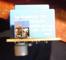
Lesson: power safety isn’t something to “implement later”.
Tips: * use terminals with paired pins for each connection, or connectors with metal casing that can be grounded; * if using stranded wires, at least tin them to prevent shorts; * have a fuse for each power user.
What’s 3D rendering good for?
If you’re wondering why would anyone want 3D rendering functionality in their EDA, just look an the lower side of the photo above. See that huge grey bulb? It’s a 1 mF electrolytic capacitor. I thought the SMD version was going to be small. And it was, compared to a through-hole. Still, a few millimeters too tall for this application.
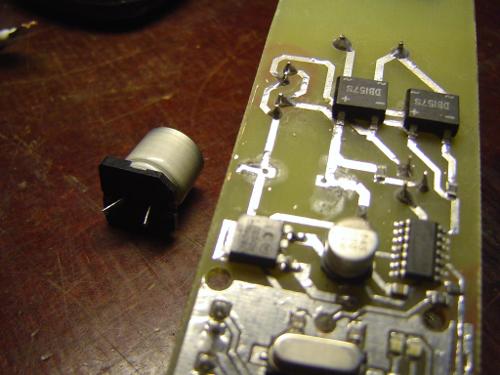
Soldered it out, drilled a few holes, bent the pads into pins, and soldered it in on the other side.
Then, there were a few spacing issues, mainly with mount screw holes. I was too lazy to go looking for a footprint as trivial as this, and used vias with fat copper rings instead. The tolerances were too small, though, so screwheads ended up getting over tracks, connectors, everything.
Lesson: think about physical design, use 3D if available (KiCAD and EAGLE have it).
Stable dimming
I’ve previously had some issues with lamp flicker. Weirdly enough, it would disappear after connecting an oscilloscope. I still haven’t figured this out, by the way. Thought it was noise in power, ground or zero crossing, but debugging led nowhere. Frustrated, I decided to do some meditative code cleanup.
Which turned out to be a great idea. It showed that timer resetting was still being done in a software interrupt routine. This creates delays, since processor state has to be pushed onto the stack first. Resetting the timer in hardware (which I assumed I had been doing all along) fixed the issue and gave a nice homogeneous glow.
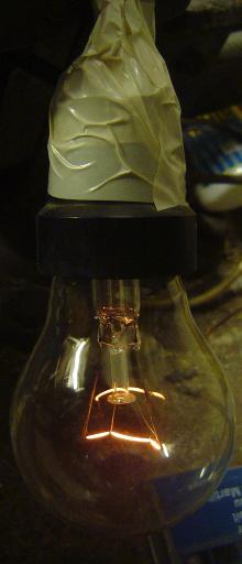
Lesson: don’t assume you’ve got things right, and check; also, don’t assume you’ve already checked; avoid infinite recursion.
Real men wind their own chokes
… mainly because they’re too expensive. The chokes, of course, not men.
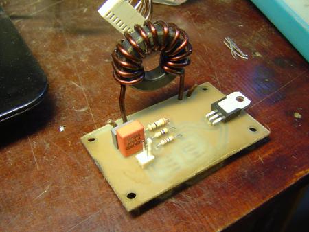
Here’s one used in a dimmer module. It’s a ferrite toroid core with 2 mm wire wrapped around it. 2 mm diameter gives a 3.14 mm2 cross section, which is slightly overkill, and definitely too tough to wind. I’d aim for 1 mm2 per 10 A. Double-wound with thinner wire, perhaps, to ease the chore.
Module overview
Here lies dmx-dimmer, with one of each modules.
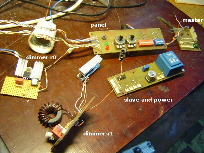
I’ve made two revisions of the power dimmer board, with different triacs. r0 was used during initial prototyping, to avoid running high currents through the breadboard. It doesn’t have a choke. r1 had some layout quirks, which made running a proper test (with a 2 kW fixture) impossible.
It also looks like a rat’s nest due to all the wires. Some were simply soldered to the board. Bad idea! Move the boards around too much – and they break. Leave them by the table’s edge – and they fall. A remarkable annoyance.
Lesson: don’t make a board unless you intend to test it any time soon.
Tips: * a triac is not symmetric, if it doesn’t trigger, you might have to swap its MT1 and MT2 connections; * soldered wire connections are not OK for prototyping.
Last notes
I have yet to measure power usage. And many other things. This will have to collect dust for a while, though – safely, inside a box. I packed it all up and went to do something entirely different. The updated designs are available at GitHub.
Strangely enough, I also stumbled upon Semitone Lighting Controllers, an open hardware project that’s been running since 2003. Somehow Google missed this last year. I would have just built a Semitone Diamond instead of doing all this!..
Lesson: don’t trust a search engine.