What’s this about?
I’ve started working on this project slightly more than a year ago, during winter. Why is a rather lengthy story. By June development was finished (almost), I shelved the thing, made a backup, picked up my backpack and headed outdoors, where fun was to be had.
What I’ve been doing all this time until now is another long story. Among other things, it involved working as an apprentice light engineer at a theatre. The dimmers there were 30 years old and took up a room ten times the size of our workshop. If I showed you the photos, you’d say it was fake, or at least crazy. The reason it’s still there after all these years is the upgrade cost.
Anyway, a few weeks ago I registered at GitHub and pushed the project there. Be warned, there’s a lot of turbulence. For example, at the time of writing, the firmware is a few commits behind the hardware – pinouts had to be changed on the Master board to keep things simple and allow homebrew manufacture. But I’m getting ahead of myself.
Wasn’t it already available?
Of course, I looked around before engaging in a project as big as this. And there’s a lot of schematics and open-source stuff available. Some are based on, you guessed it, Arduino. The closest to what I needed, though, was Hendrik Hölscher’s DMX dimmer.
But it uses a rather old AVR microcontroller, runs off single-phase, and can have no more than 8 channels. I need something with components that won’t disappear from the market too soon, something that uses three-phase mains power (but can use one or two if that’s desirable), and allows 12 channels, more if feasible.
Or so I thought up a year ago. Of course, now I see other, better ways of achieving the same. Yet, I’m too anxious to re-design, so this will have to go.
What will be inside?
All of it is organised in four types of modules.
A couple of status LEDs and an address switch are on the panel, available to the end-user. These settings and DMX512 data are received by a Master microcontroller, ATMega168, using SPI for the former and USART for the latter. The data is then distributed to three Slaves using SPI and a wacky scheme of SELECT/READY lines. These ensure the data goes where it has to, when it has to, and doesn’t get lost during time-critical interrupts. A Slave, ATTiny2313, receives its set of channel data, determines its controlled phase’s zero-crossing, and fires signals to actual dimmers, up to four of them. A dimmer opens a thyristor, which allows current to flow to the light fixture; a heavy-duty choke is involved, how heavy depends on the money or time one’s willing to spend.
At least that’s how it works right now. Tests were carried out using protoboards, and everything seemed fine. How well this scheme performs in real life, under the strain of real loads, is yet to be seen.
When will this be available?
I don’t know.
Currently, I have two other consuming projects. One of these I expect to post some time soon, too.
As mentioned before, the current state of affairs is always available on GitHub. So if anything goes wrong, at least it’s not lost forever.
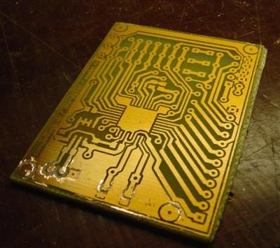
Today, I’ve etched the Master board and started populating it. Then it turned out I didn’t have a 16 MHz crystal on hand – luckily, one could be easily raised from an old computer extension board. I didn’t have an 0805 120 Ohm resistor, too – and it seems these weren’t so widely used in the days of ISA. Oh well, off to the shop tomorrow. For now, enjoy this image:
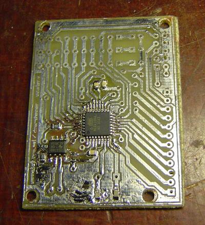
By the way, I’ve used SMD soldering paste here. The expiration date says August, 2010. Works pretty fine, though. Only had to leak off water that separated.