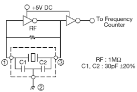
For a future project I was playing with a basic oscillator, based on inverter and ceramic resonator.
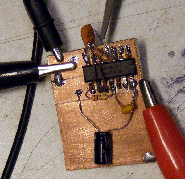
After hooking everything up on a breadboard and looking at the signal I have instatly understood it’s the fast signal domain and shonky breadboard will not cut it, so I have soldered everything on a copper clad board.
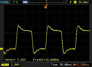
The signal looked like this. Eww where are those overshoots comming from? In spite of signal being just 12MHz, the edges of the pulses are too sharp for my measurement system to record properly.
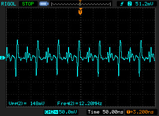
First things first. Let’s have a look at what power looks like. Wow, this looks really bad. Oscillator produces really sharp edges demanding huge gulps of current. Inductance in naively long leads of decoupling capacitors causes power rail to bounce aroud pretty awfully.
After shortening the leads, power rail looks much better. Peaks are cut in half.
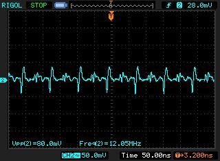
I had 100uF electrolytic and 10 uF ceramic capacitors for decoupling. Let’s add small capacitance to take care of those sharp edges. After adding 1nF ceramic cap, power rail looks even better.
Ok, let’s get back to the output signal. I was scoping the signal with 50MHz Rigol DS1052E scope, using stock Rigol probe that claims to be of 100MHz bandwidth. The probe was in X10 mode and I’ve used a short spring for the ground connection. There is less overshoot than in the picture above, but still, I’d like to get rid of it.
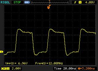
The rising edge of the signal is about 4 - 5 ns. According to the internets, to see such an edge I’d need 1/(pi * trise) ~70MHz of bandwidth. Of course this is impossible with 50MHz scope, but I wanted to do something about those overshoots anyway. Scope probe even in X10 mode has a fair amount of capacitance that plays with sharp edges and causes ringing and overshoots. Z0 low impedance probe to the rescue! If you want to see sharp signal edges, you have to reduce capacitance in the probe, this simple probe does just that.
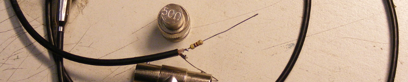
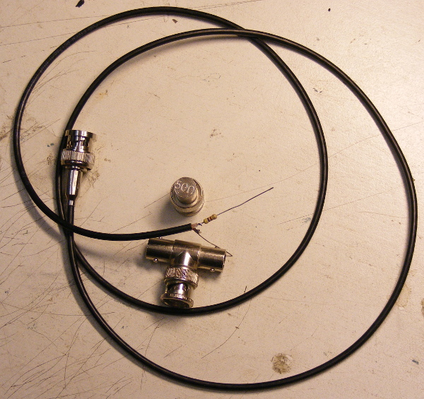
To make a Z0 probe, you’ll need a length of 50Ω coaxial cable, a coax connector, 450Ω resistor and 50Ω terminator if your scope does not have 50Ω input option.
As I didn’t have 450Ω resistor I’ve shuffled thru my stash of 470Ω resistors to find 462Ω one. This gives me X9.7 ratio - close enough to standard X10. To make a probe, just solder the resistor to the end of coax cable and put the connector to the other end. To properly terminate 50Ω cable, add a terminator at the connector end. Now you have a high speed probe.
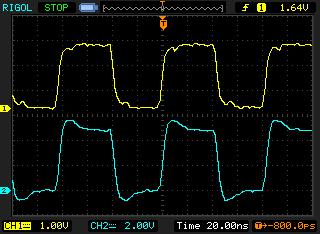
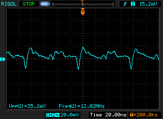
Yellow trace in this picture is Z0 probe, blue trace stock Rigol probe in X10 mode with short ground lead. As you can see, overshoots are completely gone with Z0 probe.