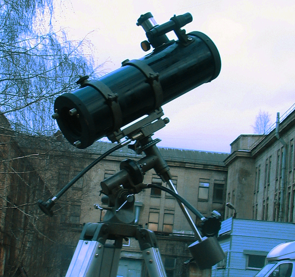
We wanted to give a telescope as a Christmas present to one kid. Luckily enough we have happened to find one standing under the autumn rain in a second hand junk yard in Berlin. The telescope itself was dusty and wet, but the mount was in a good shape, just the driver electronics for the motor were missing.
After some poking and googling I was able to determine that the mount uses a bipolar stepper motor to compensate for Earth’s rotation. How do you drive a bipolar stepper? Well, you just hook up a couple of H-bridges and let the microcontroller switch them.
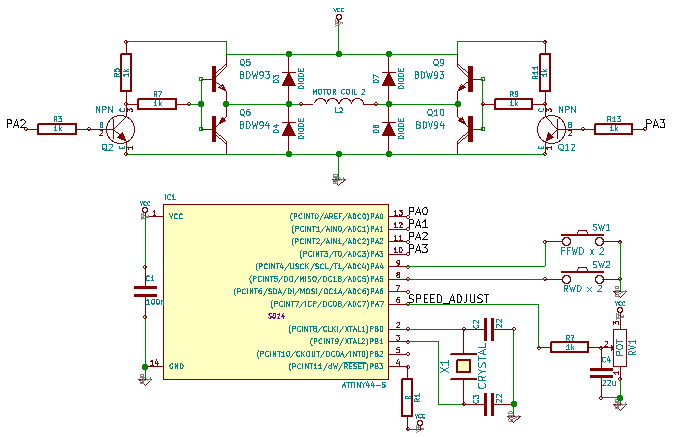
I didn’t have enought time to order parts, design and etch the PCB, etc, so I decided to use whatever I had around. The code and schematics are available on my github repo if someone wants to reproduce this or just to poke around.
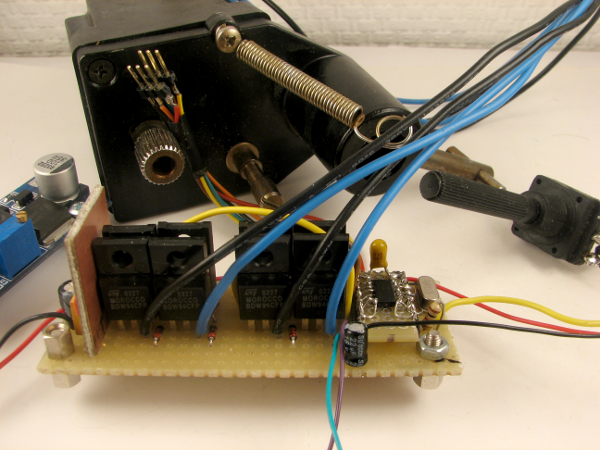
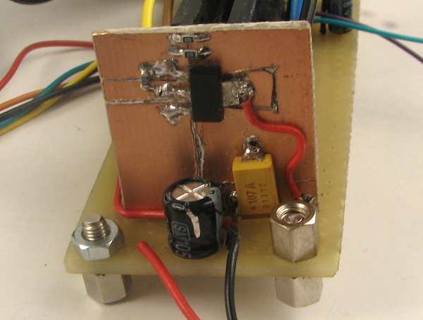
Here you can see an H-bridge circuit built using BDW93/BDW94 Darlington transistors - those just happened to be laying in my junk box after I had dissasembled some projector TV I had found on a street a year ago. It had lots of linear amplification - lots and lots of matched NPN/PNP power transistors. Probably Darlingtons are suboptimal in this application, mosfets would be better, but in the end the motor was turning and driving the whole telescope assembly at a reasonable power consumption so I guess it’s good enough.
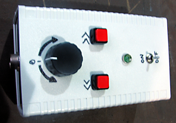
I’ve tried to reproduce the functionality of the commercial EQ2 driver. When turned on, the driver starts to turn the motor at a constant rate of 1 revolution per 70 seconds. Buttons allow for double speed fast-forward and rewind. I decided to make do without a tumbler for changing a default direction of rotation, but add a potentiometer to fine-tune the rotation speed.
I want to thank the author of this page for providing valuable information about motor rotation speeds and gear ratios.
Since I ran out of all the SO to DIP adapters, I had to deadbug the ATTiny44 micro. Not my favorite style, but it went ok.
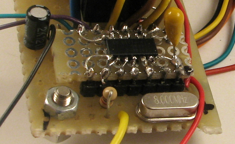
I had this LT1117 LDO board from an earlier project. The LDO was of the adjustable variety, so I hooked it up to source ~3.6V for a microcontroller.
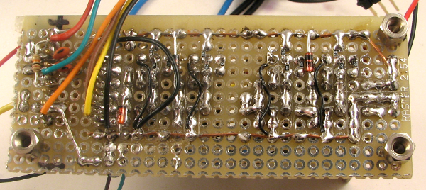
The bottom of a veroboard never looks good, but in this case I’m pretty happy with it.
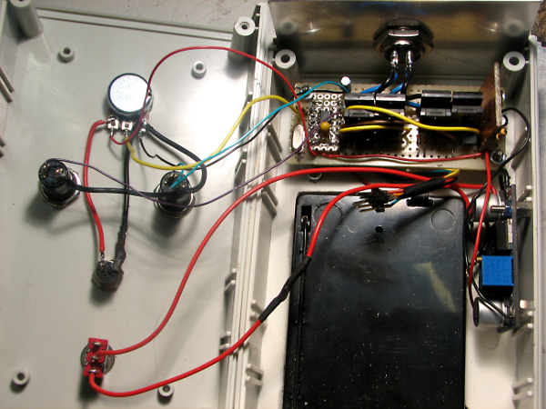
When cramming everything into a case I was repeating to myself: “I will never design a PCB without selecting a case first again, I will never design a PCB without selecting a case first again, I will never design a PCB without selecting a case first again, I will never design a PCB without selecting a case first again…”
The driver is powered by 6 AA batteries. Voltage for the motor is provided by an adjustable switching DC-DC converter based on LM2596 (a cheap Chinese module off ebay). On average it draws about 0.1A of current at 6.5V, this allows for some 8 - 12 hours of operation on one battery set.
The final driver in an enclosure looks like this
The code is not spectacular - I have an array of H-bridge switching configurations and output them to MCU IO port on every timer compare match interrupt:
//HIGH torque, high power stepping
uint8_t stepProfile2[] = {
	0b00000101,
	0b00000110,
	0b00001010,
	0b00001001
};

ISR(TIM1_COMPB_vect) {
	doStep = 1;
	TCNT1 = 0;
}

void main() {
//...
	while(1) {
		if(doStep) {
			i = i + direction;
			if(DIR_CW == direction) {
				if(i > 3) {
					i = 0;
				}
			} else {
				if(i < 0){
					i = 3;
				}
			}
			PORTA &= 0b11110000;
			PORTA |= stepProfile2[i];
			doStep = 0;
		}
//...
}