It’s that time of the year again, and I’ve been working these past few weeks on the dmx-dimmer project: putting it together on a piece of cardboard a-la science fair, re-designing the power dimmer module, and running power tests.
Last visit I mentioned winding my own chokes (inductors). These will be used for rush current suppression in the power line, so they need not be precise and uniform.
We salvage ferrites among other things, and there was enough wire laying around. If I had to buy either of these, doin’ it myself would’ve been more expensive that buying pre-made ones – provided, of course, the local shop carries them at all.
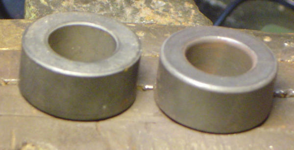
Anyway, I started out by smoothing the straight edges on my ferrites, otherwise laquer on the wires would’ve gotten damaged during bending, which means spark gaps. Used a small round file for the first one, but it took too long, so switched to a hand-held rotary tool with a sanding stone drillbit. On the image below, the smoothed toroid is on the right.
Then I cut two pieces of 1 mm copper wire, both 90 cm long (determined by trial). I removed laquer on their ends using sand paper, since none of the solvents we had on hand worked. ioch speculated it could be done in boiling base, but we haven’t tried that.
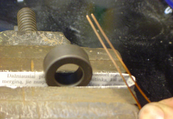
I clamp the ferrite in a vise with some padding, put a pair of straigtened wires through the hole and, well, start winding. This requires both hands to constantly press the wire to the ferrite, keep gaps as small as possible, prevent wire arcing and bending, get equal spacing and many other things that take many other words to describe.
If you intend doing something like this, I suggest practice first. There’s nothing about chokes but getting the hang of it.
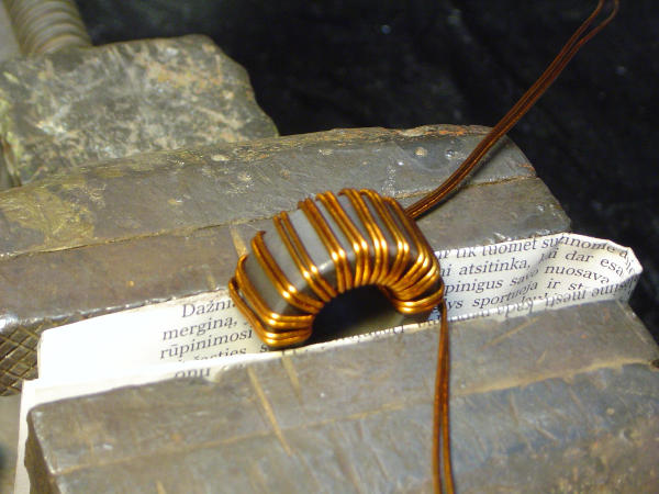
After one half is done, turn it around in the vise. Ideally, it should be perfectly symmetric when finished. In practice, one of my first chokes looked something like this:
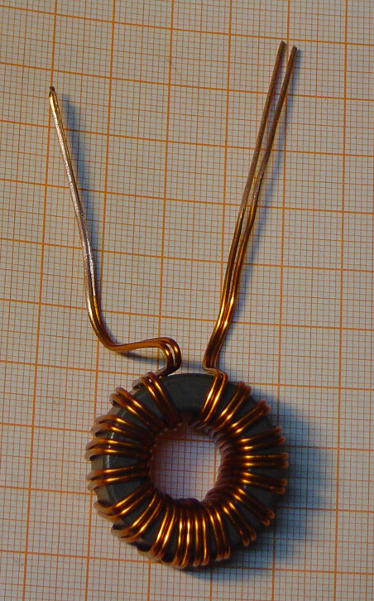
Not too bad, really.
Before I solder them into the boards, I decided to check if any laquer got damaged after all, and see if they burn. So I cut them into the phase line of the mains, one at a time:
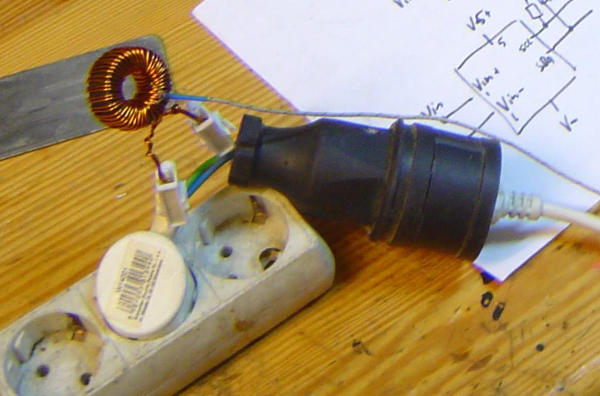
On the other end sits a 2 kW load of light fixtures. The chokes heat up to 40 °C. The blown socket in the picture above is from an unrelated experiment.
I’ve also tested one with the new dimmer module, and it works, but noisily (as in sound). Which means I’ll be dipping them into epoxy.
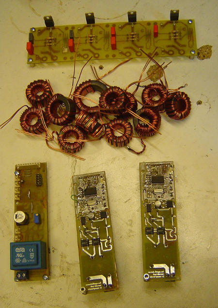
In the image above, from bottom to top: three populated slave boards; a dozen chokes; and one 4-channel dimmer board, missing a few caps, a few headers, and the inductors, of course.
As always, all design files are available on GitHub.