Introduction
Gotta get off, gotta get off, gotta get off of this merry-go-round…
This is another big one, and it came in together with the rails, so you can guess why there ain’t many pictures. We had our hands full of tools more labour-worthy than a camera.
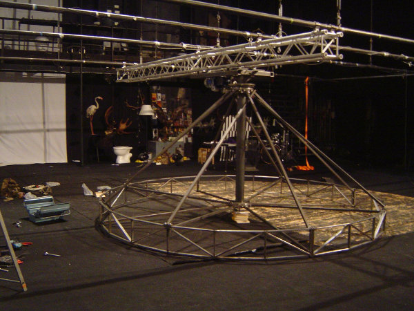
Anyway, a carousel was to be made in little no time. It had to be 4 meters across. It had to spin, at various speeds. It had to sync with a revolving stage. It had to be stable enough during rotation that articles of fine modern furniture could be suspended from it.
My part in this was the rotating circle and its suspension to the axis. The rotor, in short.
Blueprints? What blueprints? (A FreeCAD review)
In short: there were none.
For all I intended to do, I really wanted some: we’re talking circles here, people! Lots of angles cut at precise lengths, and most of them in volume. But, alas, every artist is his own engineer.
I tried some open-source CAD programs, spending most time on FreeCAD (version 0.12.5284), and the verdict is: not stage-ready.
First off, FreeCAD is a front-end with frills, written in Python 2 (and Qt). The back-end is OpenCascade. There are big issues with both.
The biggest one with me is this. Since FreeCAD is written in Python (essentially a prototyping language, in my view), it breaks a lot. My system is probably quite different from that of the current developers’, and it dumped core once every three minutes (on average). Filing bug reports would have been useless: there were at least ten different exceptions in trace-backs, and we would have spent hours arguing whether this is a misconfiguration. Of Python.
If you do decide to try out FreeCAD, have the following in mind.
-
Do not upgrade your real work parts to a combined part, upgrade copies instead and hide the originals. If you decide to edit the combined part later, exploding it will give you
fecesfaces instead of solid objects. -
Making a lot of copies at once might not copy everything, but it fills the object list anyway. Deleting objects that are listed but don’t exist drops core.
-
It seems there’s no way to specify an arbitrary reference axis when rotating, which caused me a lot of grief.
-
You either rotate in the current view’s plane, or one of pre-defined XY/XZ/YZ, which are also called top/front/side elsewhere. Confusing.
-
Rotating multiple objects in the same plane by a certain angle does not always result in them rotating the same angle. If it sounds wrong, that’s because it is.
-
Snapping uses algebraic units and doesn’t take the current view’s zoom level into account.
-
A lot of essential functionality is implemented as macros, which are not included in the basic package. Solid Sweep proves useful, if you can get used to it.
-
Boolean operations on solids do not always work, which is mentioned in the FAQ.
-
Also, they sometimes drop core.
After several hours of cursing, I got this.
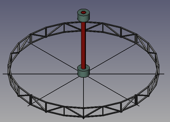
Which is, in my book, too long for too little. I eventually drew and calculated everything I really needed on paper.
Why not AutoCAD? Because I don’t use Windows. Why not Google SketchUp? Because that doesn’t have Boolean operations on solids in the freeware version. Why not DraftSight? Because that has very limited 3D functionality. Why open-source? Because we don’t really get anything but experience points for this.
Sorry for the long-wrought review, I just had it sitting in my home dir for three months. Back to the topic.
A slice of Pi
As soon as metal got into the shop, I set out to cut those beautiful long slender things into stacks of beautiful short identical things.
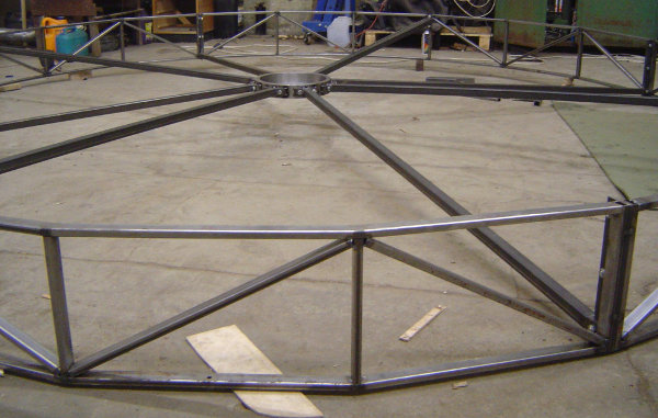
Remember, it’s a “circle” 4 meters across, made of short straight segments. A polygon, right. The circle’s perimeter is d * π = 4 π. We decided 24 corners is circular enough.
Technically, it was possible to take a square pipe blank and roll it to achieve desired curvature, but we don’t have the equipment, and there were no resourses to order from a specialised shop.
As always, we designed it so that it could be taken apart (into four parts). This has a few advantages.
-
It takes less space in the storage room when not needed. You don’t hang stuff you don’t need from a high ceiling, do you?..
-
It fits through the workshop’s door, and also into our painting chamber, in case we had time and paint to paint it (we didn’t).
-
Splitting the circle into four arcs that have a length of π is a nice inside joke. It lets us feel like we know what we’re doing.
I then tack-welded these pieces into eight arcs, and tack-welded those parallel, in couples. It didn’t go too well. I made a jig to weld the short segments together into long arcs at a precise angle. The angle was good, but the jig was too short – it could only support three segments until the arc would start to curve due to its own weight. I set up a convoluted system of props to keep the dangling end from bending too much. This unwanted curvature was reduced somewhat, but still demanded an array of clamps to hold paired arcs together during welding.
Long story short: I was too lazy to set up one proper jig, and so had to set up two instead.
eggman cut and drilled eight plates for segment connections. In the image below, you can see the four tack-welded segments, clamped together with the plates in between. The clamping was also needed for alignment. Luckily, it was just tack-welded, which allowed for fine adjustment (two holding and one adjusting with rebar). The hammer, fridge and van are for size reference.
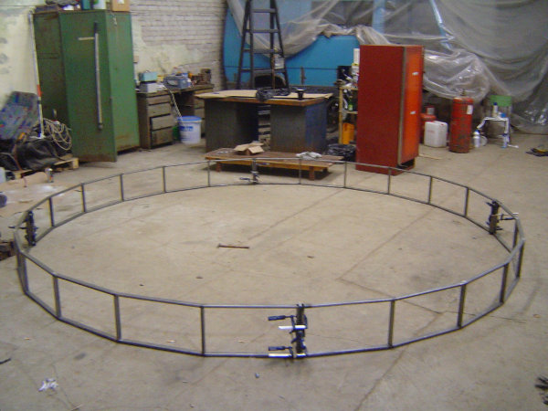
Most of it was rectangular profile, 30x15x1,5 mm. Pretty lightweight, and considerably more flexible along its 15 mm side compared to the 30 mm side. 6 pieces per arc, with end pieces slightly shorter than the middle ones, to accommodate the thickness of the connection assembly. The connection plates are just lengths of a wide strip, something like 5 or 6 mm thick. It will be slightly clearer from later images.
Suspension: lower bearing mount
The axis at the center had two machined bearing mounts, one at the top, one at the bottom. The circle connects to both with a total of 16 profiles (30x30x2 mm). We called them “strings”. 8 strings to the top, 8 to the bottom.
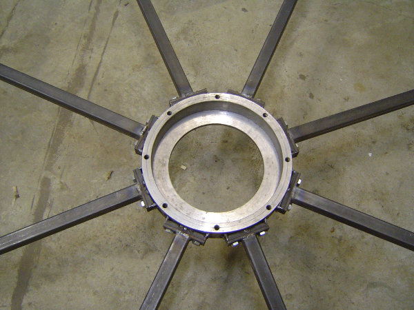
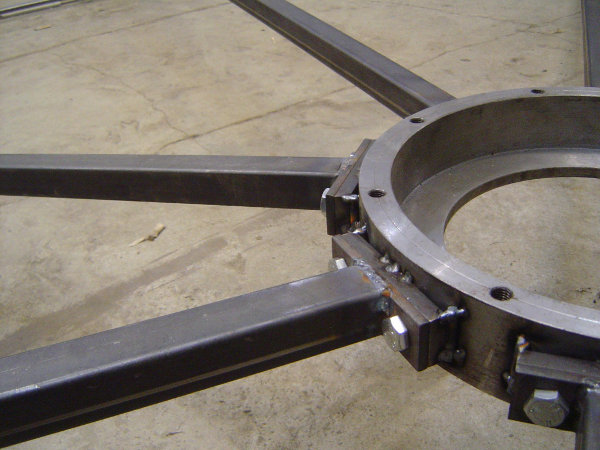
I started with the bottom mount, once again only tack-welding connection pates to the side.
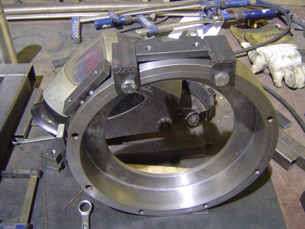
There were holes for the bearing’s lid in the mount, which came handy for a kind of piggy-back-ride alignment job: screw on two alignment brackets, put a connection plate in the middle, tack, turn, repeat. It is hard to see in the image above, but there are also two pieces of metal, cut to the same length, held at the other side of the bearing mount with welding magnets. So the connection plate is right in the middle. It turned out later most of this wasn’t exactly necessary, and the connection plates could have been welded at the edge just as well.
I then put the bearing mount in the middle of the circle, cut four strings, with different angles at both ends, and welded plates with holes to those. Then four more strings, with yet another set of angles. It came together like this.
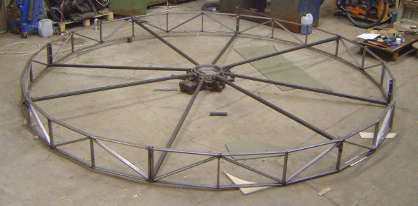
What I leave out of the picture here is engineering: measuring the exact angles and lengths, taking the thickness of connecting pates and plane rotations into account, and all the running back and forth in between.
Four strings connect to the top of the circle at the middle of its segments, and four more connect to the bottom where segments meet.
What’s also different is we put in diagonals into the rectangles, to improve rigidity. It would have probably been even better if they were put in rotated 90 degrees along their own axes, so that the 30x15 profile’s flat side was co-planar with the circle’s imaginary cylinder. That would give rigidity in a plane tangent to said cylinder’s surface. But it would also mean we’d have to cut the ends of the diagonal profiles at two different angles, four times per diagonal, a total of 96 cuts. There was no time for that.
Inside the circle’s angle
I must have been waiting for something, since I have many pictures of this stage.
Here’s another angle of the previous photo. It shows a closer view of all the connections mentioned thus far.
Here’s how the pie segments connect:
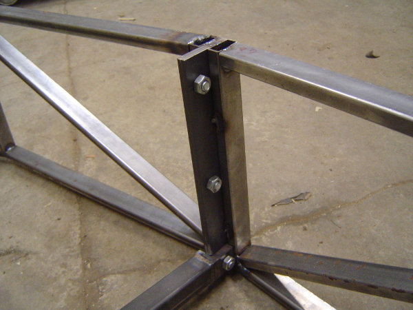
Connection plates have three screws. This way, you can always take one screw out, and the other two will still be holding the thing together.
Also visible is one end of the lower string, screwed to the segment’s connection plate. Since a screw hole was available here, we thought it could as well be used for something other than just sticking two circle segments together.
It wasn’t so easy in the middle of the segments, where the other four strings go:
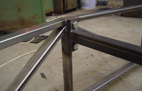
An additional (thick) plate had to be welded to the (thin) profile here, and inside the circle’s angle. Took some fiddling, and I eventually settled on high-frequency pulse welding.
It all comes together at the bearing mount:
There were also pieces of rod under the connection plates, to fill the gaps:
Stator and axis
What I was waiting for was for the stator and axis assembly to be finished. pwf did all of it, except for a few small parts I made while there was nothing else to do.
We initially planned the axis to be 2 meters high, but later settled on 1,5 m to reduce weight. This quickly proved to be the right choice, since the entire length could be reached from the floor. A shaky ladder was involved, sure, but only later on, during some final welding, and wasn’t required to hang the stator on a girder.
Anyway, here it is, upside down:
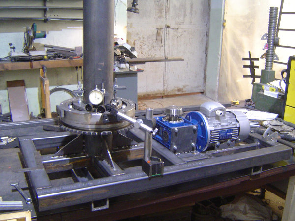
On the right is the motor and gearbox. On the left, the axis and upper bearing mount. The latter’s alignment is being checked.
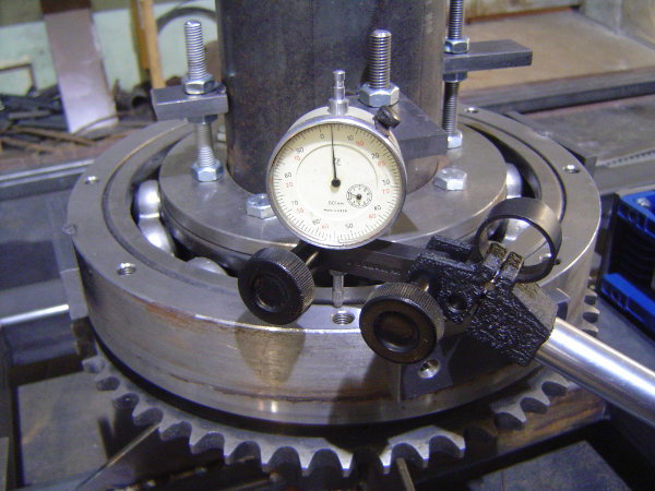
In the measured plane, the maximum deviation was 0,032 mm.
I’ve also tacked four plates for strings to the upper mount by this point.
Death march
We were running out of time, so there are no more pictures of the build process. I’m also not sure what happened after what exactly.
What I do have on the hard drive is many pictures of couplers.
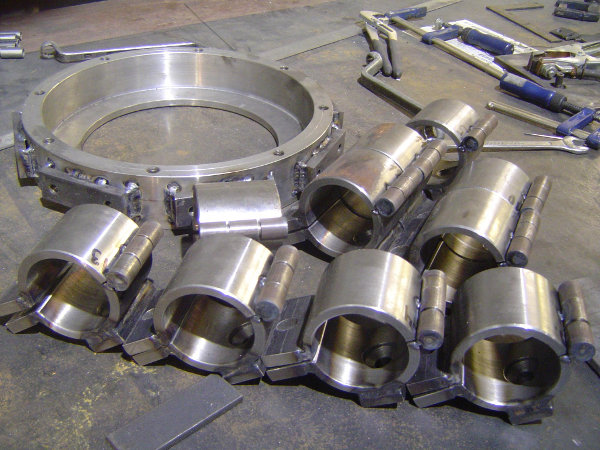
These would eventually be used in suspending the carousel. Can’t tell much about why and how many, since I had nothing to do with it. There were 16 of them, I think. I do remember various artists cutting machined cylinders lengthwise.
Also visible is the lower bearing mount, with plates welded all the way.
Fast-forward to a full assembly, past the night when everything that was tacked got welded.
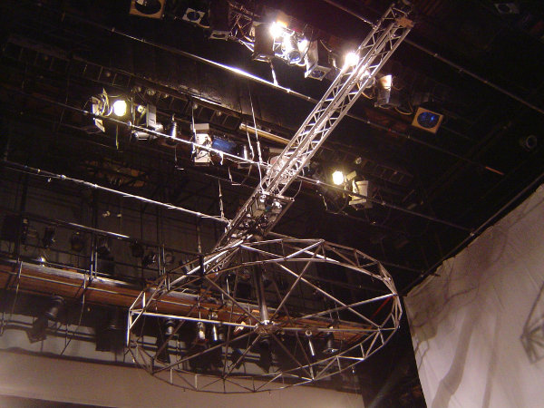
Eight more strings, to the upper bearing mount. Four of them straight, just as the lower ones. Four more at a tangent to the upper bearing mount, an almost 90° angle, because we thought this would be useful in rotation moment transfer. A few helical spirals would have been better, of course, but that would have been too much.
Several couplers are also visible. Well, almost. The hatched system of battens is required for weight distribution. When lifted, the merry-go-round’s rotation may introduce swinging, so the pipes have to be attached to a static structure with strip belts (one, orange, can be seen hanging in the image above).
Here it is again, in all its glare:
What’s not in the description
Everything mechanical and electrical – essentially rotation and synchronising with the revolving stage. Also, everything that got hung (a Styrofoam closet can be seen, though). I was not involved in those parts.
I did manage to get a few crappy videos, though.
First, stuffed animals spinning at half of maximum speed.
Second, rotation tracking. A stuffed flamingo is propped up on a box that stands on the stage, and suspended from a cord that is attached to the carousel at the same time.