Update 2012-11-30 A new working vesion of plant watering alarm is available for sale! It’s open source and it goes Chirp!
So I’m building the new version of my Plant Watering Alarm. I’m doing it based on capacitive humidity sensing - damp soil acts as an electrolyte increasing the capacitance of some makeshift capacitor made of couple of traces on PCB. I’m currently just counting amount of processor ticks while charging the capacitor till 0.63Vcc and it’s working quite OK, but a few days ago I have stumbled on this technique to measure capacitance:
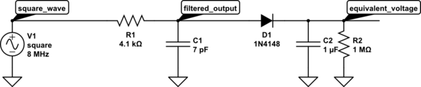
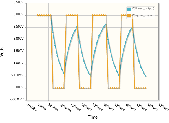
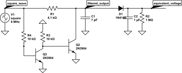
Idea is straight forward - you feed square wave into low pass filter composed of a resistor and your probe as capacitor C1. As capacitance of C1 changes, so does cut off frequency of this low pass filter, lowering the peaks of output waveform, then this kinda-triangular waveform is rectified by a diode D1 and a capacitor C2 to give voltage estimation of capacitance of C1. Here you can see an approximation of what I saw on my shabby analog scope:
I’ve instantly put together a circuit using 555 timer to generate a square wave. While playing with the circuit I’ve noticed that when I increase C1 or R1, peak values do not go lower linearly, then I’ve noticed, that capacitor does not discharge fully as square wave is exactly 50% - so the peak-to-peak value is changing, not zero-to-peak. This creates some problems as voltage on the rectified output would not swing as much as it could, we are loosing dynamic range…
The fix was easy - just discharge C1 on zero phase of square wave. You could use a PNP transistor for that:
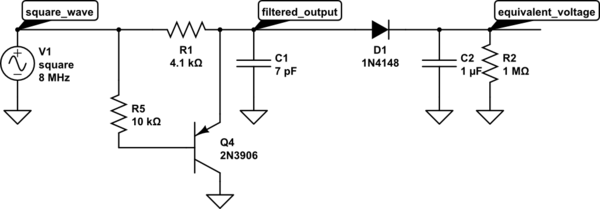
It looked much better on the scope, but there is one slight problem - emitter-base junction will conduct until there is more than 0.7V difference between them. So, I’m left with constant 0.7V on C1 after each charge/discharge cycle. Ok, lets use two transistors:
Q3 acts as a logic NOT component outputting HIGH, when the square wave goes LOW - this turns Q2 on really hard and capacitor discharges until it reaches Vce of the transistor which is much lower than 0.7V. OK, so far so good, I can go on with calculations: what is the most optimal value for R1 so I would have the biggest voltage swing in my capacitance range? Here comes The Formula (taken from the great Electronics Tutorial about the RC Time Constant):

Vc is voltage across capacitor, Vs is square wave HIGH voltage, t is time, R and C are resistance and capacitance of your RC network. OK, lets put it into Wolframalpha:
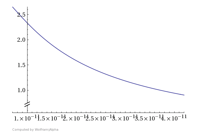
This is a graph of Vc for t=62.5ns, R=4.1K and capacitance from 7pF to 42pF as this is my current probe capacitance range when in air and when fully submersed in water. Not too linear, but oh well, tradeoffs must be made.
I know 4.1K is optimal because of this graph:
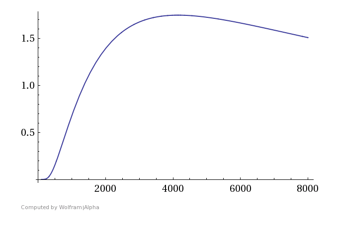
On Y axis there is a voltage difference between points at 7pF and 42pF and on X axis is resistance of R1. Heck, I can calculate that precisely:
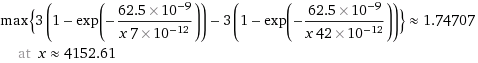
So, optimal value for R1 is 4.1K and voltage swing is from 2.66V to 1.57 minus the diode drop. The response is not linear, so R1 could be chosen smaller so the graph would shift to more linear region or it can be handled in software.
On final note, I’m yet to build a prototype based on this technique. I’m not sure if all of this will go into Plant Watering Alarm as it’s working quite ok in its current iteration. 1.75V is 1.74/(3V/1024)=596 values on Attiny44 10 bit ADC, it could be improved by adding an external voltage reference or doing some op-amp shifting/scaling kung fu, but it’s not really feasible for such a simple device as Plant Watering Alarm is ment to be. Maybe I will get on building a high end soil moisture probe, so let me know if you would be interested in that.
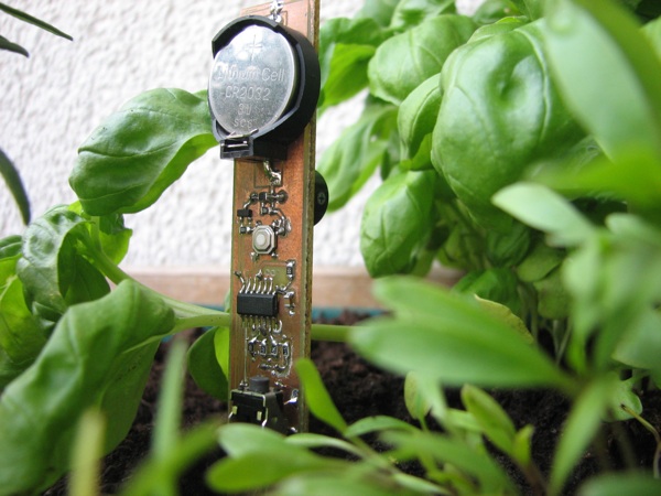
Meanwhile here’s a sneak peak preview of current iteration of Plant Watering Alarm: