Ado
Purchased this card last year, as part of a long-overdue workstation upgrade. By then a two-year-old model, it has become sufficiently uneconomical to krypto grinders to drop into my price bracket.
Somewhat ironically, the heaviest loads it’s seen from me was same old mining (hey, someone’s got to work those testnets…). Wisened by past experience, I gave it regular (monthly) compressed air cleaning.
Eventually, though, the system started experiening crashes/lock-ups,
becoming completely unresponsive to inputs - NumLock toggling, pings,
anything. An identifying feature of these was the main (HDMI) screen
turning a deep green color, the secondary (DVI) screen going blank (if
my memory doesn’t fail me), and the GPU fans switching to 100%.
I took online to find the cause, but only found people (mostly gamers of graphics-heavy shooters or simulations) having the same problem on the same model - not necessarily the same manufacturer, - as well as a few same-generation AMD-based consumer-grade models; and, after much fiddling with drivers, OSes, distributions, and mystic incantations, returning them for a refund.
Looks like overheating to me
By then, I was already running Prometheus and its Node Exporter to collect system metrics, albeit the collector was on the same machine.
Without load, the card was showing around 69 °C. Under load, it would climb towards 85 °C or so, never quite reaching it prior to a crash.
Once, due to some fluke of luck, the system managed to log 700 °C on the GPU thermal sensor. The number itself, of course, is bogus: what amazes me is that Node Exporter managed to read a garbage value from the sensor, that got collected by Prometheus, then written to RAM cache of the time-series database, and flushed to disk!.. (Actually, plural - disks, a software-managed RAID array…)
Anyway, that corroborated my suspicion that thermal paste on the GPU has dried out. I decided to void my warranty, so that the Internet could get this settled.
Disassembly
Since I was so sure of my conclusion, I didn’t take many pictures.
(If you’re repeating this process: start with the screws on the back/board side. On my model, the front mostly covers the fan assembly, so unless you’re changing the fan, there’s no need to go there.)
Here it is with about a month’s worth of dust accumulation on the radiator fins, and nine months worth on the “inside”:
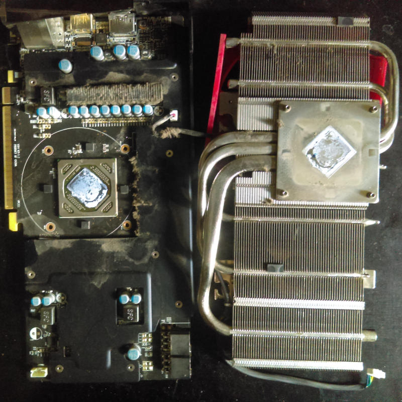
The thermal paste was caked, and didn’t take much force to remove with a plastic spatula. (If you’re having trouble separating the two parts, do check if you missed a screw first!)
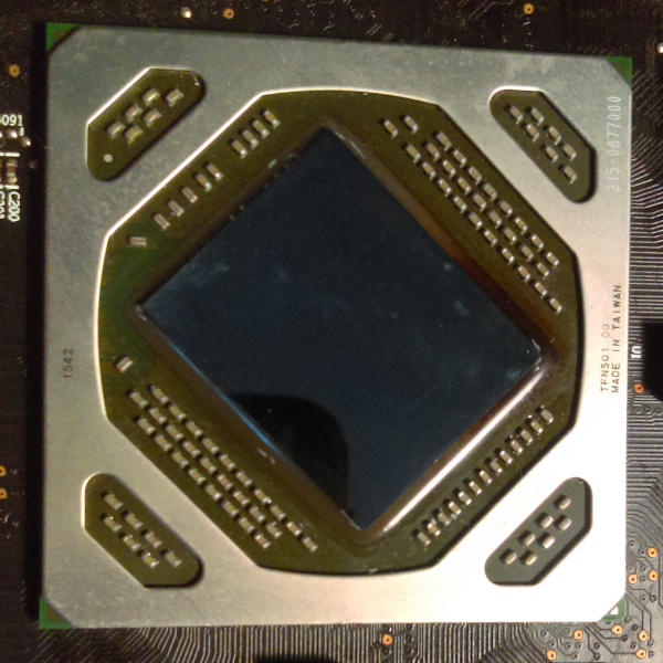
Below, see discoloration (blackening) of the compound used to secure the ASIC to the board - a tell-tale sign of overheating:
I applied new thermal paste, and put the thing back together.
After that, the machine shows around 60 °C under no-load conditions, about 66 °C playing simple puzzle games, and 72 °C grinding on the Ropsten test network.
What’s the take-back here?
Seemingly, my card had pretty mediocre thermal paste. If you’re experiencing the “green screen of death”, yours might, too. Unless you’re willing to void your warranty, take it to a service center.
What also amazed me was that the card did work under no-load conditions, even with the paste dry. My only guess for the reason is that the heatsink assembly is pushed against the chip by spring-loaded screws, so there’s always some contact between the two, even if not ideal in terms of heat transfer.
Either that, or the fact that I have the computer case mounted upside-down on the wall, and gravity is somehow involved (as it most often does).
“Try rotating your computer” doesn’t sound like sane advice, though.