A local band called “Sheep got waxed” has approached me with a proposal to create some interactive stage lighting effects. It had to be transportable and adaptable to different stage settings. Well, what can one do? Let’s blink them LEDs! We agreed to make 16 individually controllable white LED strips and distribute them amongst the musicians, playing animations trigerred by the music being played.
The first requirements description of the system went like this:
- 3 differential pro-line level audio inputs each for one channel
- 16 LED outputs
- 5, 5, 6 LEDS assigned to channels
Audio level trigger is automatically set to 2/3 of full range.
One of 5 effects can be assigned to each channel by the means of a rotary switch, one potentiometer is available for each channel that is used to control an aspect of the selected effect
Available effects: * VU meter - LEDs blink as in an audio VU meter, the potentiometer controls the total brightness * Triggered VU meter - channels light up and turn down in a row on a trigger, just like VU meter. Potentiometer controls the speed of the effect. * Chase - channels light up one by one in a row when triggered. Potentiometer controls the speed of the animation. * Blink - all channels fade in and fade out simultaneously on trigger. Potentiometer controls the speed of the fading. * Random - all channels blink randomly for a duration set by potentiometer.
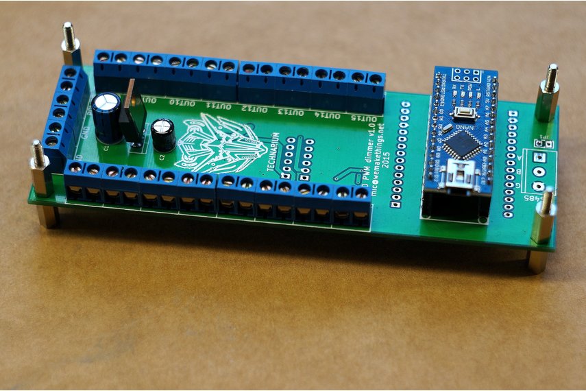
For the main controller I’ve chosen the TLC5945 breakout board I made recently. TLC5945 is a nice chip providing 16 channels of 12-bit PWM goodness. The board has a socket for Arduino Nano, a footprint for RS485 transceiver and a bunch of screw terminals.
THAT1247 was chosen as the audio front end. It’s a go-to no-brainer part when you want to do a differential line level signal translation. I did not want a journey while rolling my own, so I picked this part. I used a 6dB part and configured it as an amplifier to increase signal level. This is what the point-to-point soldered board looks:
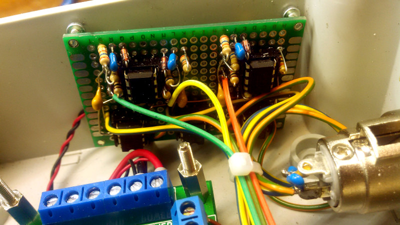

The U2A opamp creates the virtual ground midpoint. U1 receives a differential pair and creates a single-ended signal around virtual ground. Single ended signal is AC coupled and limited by diode D1 to apply only positive peaks to ADC input. Capacitor C3 and resistor R4 form an antialiasing low-pass filter which is buffered by U2B. R5 and D2 are there to protect MCU ADC input from overvoltage. I was going to run ADC at 250kHz, this allowed me to sample three channels at roughly 6kHz, this means our Nyquist frequency is 3kHz – that’s what determined my choice of R4 and C3.
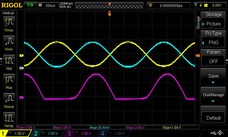
This is what it looks on the scope, yellow and blue are inputs, magenta is what an MCU sees:
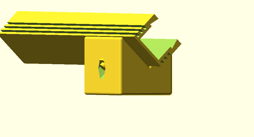
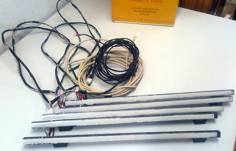
The segments had to be put on the floor at 45 degree angle. I have had a go with OpenSCAD to model the 3D printed stands for them. This was the first thing I’ve ever designed and printed.
Since we have plenty of those, I have used a Chinese Ebay “LED amplifier” on each strip. Inside it looks like a dumbed-down RGB dimmer version with a Chinese microcontroller and a MOSFET. It acts like a transistor - when you power a pin, it switches the other two on. As one needs to provide at least 12V to switch, they are robust enough - no crosstalk problems whatsoever when running 6 channels on one cable.
Wiring is a mess as I couldn’t think a of good way to provide power and data to strips with quick-disconnect connectors, so I made it the dumb way. 2x0.75mm2 cable was used for 12V and 8 wire UTP for control lines.
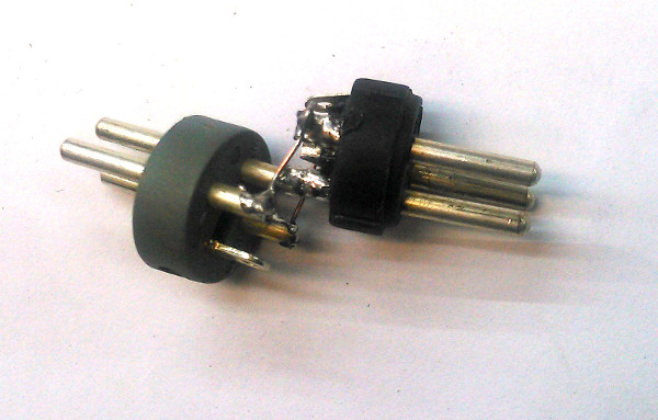
In the middle of the project I have decided to ditch the switch and potentiometer idea - musicians have enough stuff to do on stage anyway and lighting is a job of the lighting engineer. All the parameters of the effects now were to be controlled via DMX from lighting console. That’s where having a spare RS485 footprint became handy. A thing to note - audio XLR inputs are female by convention, but DMX inputs are male! I did not expect that, so I had to make this adapter to hook up the DMX.
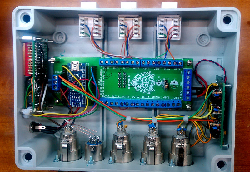
I used the 74HC165 serial shift in register to read the dip switch for the DMX address and test modes. This didn’t work in the beginning as it appeared that the SPI comm was breaking TLC comm somehow. There was no time to debug that since we were going live in a couple of days and those couple of days were the Christmas Eve and co. So I gfell back to bitbanging to read the dip switch. It seemed the SPI bus could not be used while the TLC chip library is actively pushing data.
Then I assembled everything into a box. I’ve tried my best, but not every part is pretty, especially the square holes.
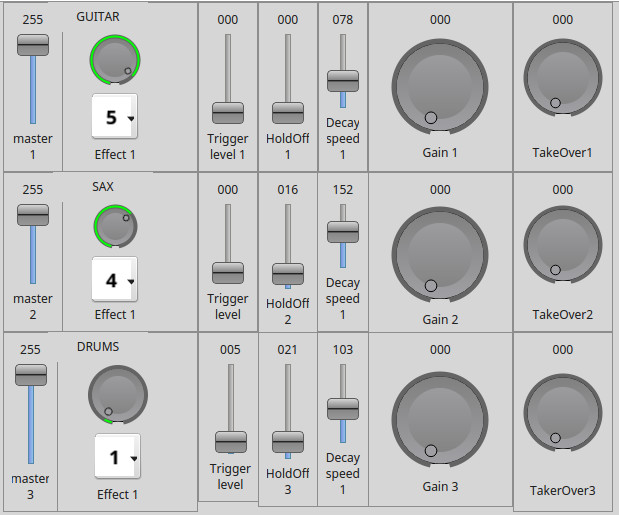
I have leveraged a wonderful program QLC+ for control - we worked together with the band and the light engineer to expose as many means as possible for controlling the effects over DMX : - Effect – the effect style - Trigger level – the level of audio which triggers the effect - Trigger hold off – time to now trigger after triggering - Decay speed – how fast the effect fades - Master – max brightness level - Gain – audio input level multiplier
All in all everything went as expected except for a couple of hot fixes I had to make just before the show and a crash. I must say I still hate the wiring - a battery-operated wireless solution would have been a proper thing to do. All the code and documentation is on my github
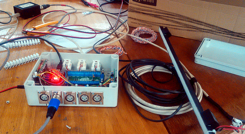
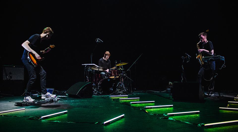 Foto by No Photography