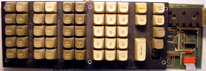
ioch had a go at disassembling a Gas Chromatographer with Flame Ionisation Detector made by HP in its glorious days - date codes on chips go back to 1975. Except misc PCBs with gold-plated tracks it contained various interesting bits and pieces of hardware, including this reed switch based keyboard.
Somehow we have decided to spend a Sunday poking at it.
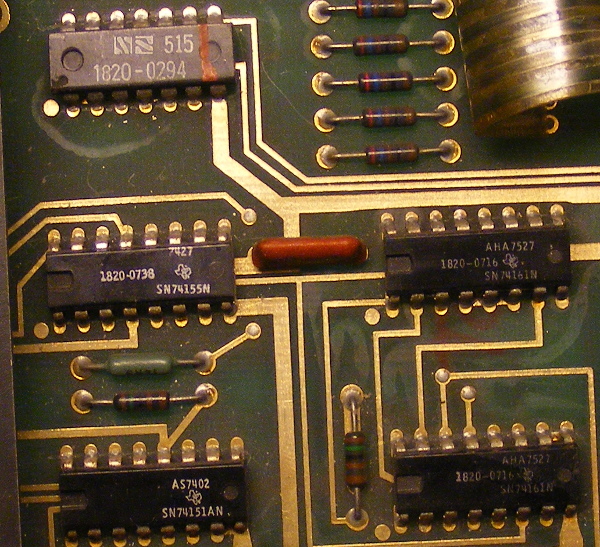
The keyboard has a couple of SN74161 binary counters, SN74151 8-Line To 1-Line Data Selector and a SN74155 demultiplexer on it.
We didn’t care too much about internal workings of the thing, rather concentrated on what’s available on the connector:
- CLK of SN74161 counter
- LOAD, ENT, ENP of SN74161 counter tied together
- QA of SN74161 counter
- W of SN74151 data selector
- D6 and D7 inputs of SN74151 multiplexer
- 2Y3 output of SN74155
So, how would you read the keyboard with the interface provided? We would pull LOAD/ENT/ENP line high to reset/enable the counter, then provide clock for it and hope the W output of the multiplexer will go high at some point if a key is pressed. Different number of clocks before W goes high would correspond to a different key being pressed. Needless to say we were right. The keyboard really was pulling W high after receiving some clock pulses, depenging on the key being pressed. The only problem was that it was acting in a way we’ve called “a statistical keyboard” - the number of clocks would jump around a couple of values randomly, but at least those values were different for different keys pressed.
So we experimented more and discovered that pulling D6 and D7 high makes the number of clocks to stay constant and even key “0” correcponds to 0 clocks, “1” to 1 clock etc.
Also we’ve traced another board to which the keyboard connects and discovered that D6, D7 lines go thru a couple of fancy looking reed relays which route them back to 12 pin of SN74155 - 2Y3 output. We’ve tried imitating those relays by shorting D6 D7 to 12 pin, the result was that keyboard would be stuck to some defined value not reacting to key presses. Weird. Why would they have a couple of shmick relays on a separate board to do that?
Anyway, so much for the keys. In addition there are 8 LEDs on the keyboard that are connected to some custom HP chip with 515 marking on it. We guessed it was some kind of shift register and were right at the second try.
Maybe we will use this keyboard as UI for one of our electric kilns.
Here goes the Arduino code from the experiment:
#define CLK 6
#define LOAD 7
#define W 4
#define D6 9
#define D7 10

#define LED_CLK 8
#define LED_DATA 5


void setup() {
  Serial.begin(9600);
  pinMode(CLK, OUTPUT);
  pinMode(LOAD, OUTPUT);
  pinMode(D6, OUTPUT);
  pinMode(D7, OUTPUT);
  pinMode(W, INPUT);
  pinMode(LED_CLK, OUTPUT);
  pinMode(LED_DATA, OUTPUT);
  digitalWrite(W, HIGH);
  digitalWrite(D6, HIGH);
  digitalWrite(D7, HIGH);

  digitalWrite(LOAD, HIGH);
}

void bangLeds(byte value) {
  byte j = 0;
  for(j = 0; j < 8; j++) {
    digitalWrite(LED_DATA, (~value >> j) & 0x01);
    digitalWrite(LED_CLK, HIGH);
    digitalWrite(LED_CLK, LOW);
  }
}

unsigned long i = 0;
byte keyCode = 0;
byte j = 1;
void loop2() {
  bangLeds(j);
  j = j << 1;
  if(0 == j) {
    j = 1;
  }
  delay(1000);
}

void loop() {
  digitalWrite(CLK, HIGH);
  digitalWrite(CLK, LOW);

  if(HIGH == digitalRead(W)){
    keyCode = i;
    Serial.println(keyCode);
    bangLeds(keyCode);
  }

  i++;
  if(i > 63) {
    digitalWrite(LOAD, LOW);
    digitalWrite(LOAD, HIGH);
    i = 0;
  }
}