From time to time I get requests to make some high power switching, so I decided to design a solid-state relay that could handle a lot of different situations. The most common use for it I have is refurbishing old ceramic kilns. Since our technical life is close to the stage (both theatre and music), I also wanted it to be usable as a dimmer module. And, just for kicks, as a single phase AC motor speed controller, in case we would want that.
So here it goes. The design and code are on github: https://github.com/Miceuz/triac-bloc. I still have some spare boards and parts if anyone is interested - drop me a note (mic at wemakethings.net). Update 2014-06-05 since people are still interested in this, I’ve decided to make triac bloc available on Tindie: 
Features:
- maximum power - 6kW
- zero crossing detection
- controllable via I2C protocol
- linear output power control
- phase shift dimmer mode
- switch at zero-crossing mode
- output filtering for dimmer mode
- snubber network
- “low level” zero-crossing signal output
- triac trigger signal input
- 4 spare MCU pins available for additional features
- open source hardware and firmware
Since deep in my heart I’m still a programmer, I wanted digital control that would solve some issues, like being able to set the output power in a linear manner. But nevertheless, the module is still usable without a microcontroller - zero-crossing and turn on signals are available on a separate header on the board. You can add or remove components based on particular needs. No need for dimming or motor control? Skip the filter choke and snubber. Want to integrate it into existing digital solution? Skip the micro and use zc and trigger signals directly.
Syncing MCU to the mains frequency
When designing a board I went cheap and didn’t add a crystal for oscillator - “it will run just fine on the internal one” was my thinking. While assembling the board it hit me - how the hell I’m going to keep the precise timing if my oscillator is off?
Fortunately, ATtiny supports internal oscillator frequency tuning by adjusting the OSCCAL register. What’s cool is that this allows me to tune perfectly into the mains frequency! And it can retune itself to account for temperature drift! Everything went better than expected. This is how I’m doing it:
inline void adjustOscillatorSpeed() {
if (oscAjdustDelayCounter++ > 128) {
if(periodLength > 10060) {
OSCCAL--;
calibrationGood = false;
} else if(periodLength < 9940){
OSCCAL++;
calibrationGood = false;
} else {
calibrationGood = true;
}
oscAjdustDelayCounter = 0;
}
}
inline void calibrate() {
uint8_t calibration = eeprom_read_byte(0x00);
if(calibration != 255) {
OSCCAL = calibration;
}
while(!calibrationGood) {
ledOn(RED);
_delay_ms(300);
ledOff(RED);
ledOn(GREEN);
_delay_ms(300);
ledOff(GREEN);
}
eeprom_write_byte(0x00, OSCCAL);
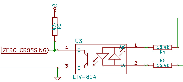
}Zero crossing detection
I chose the cheap way of doing that - just a pair of resistors and an AC optocoupler.
This works pretty well, but introduces some weird behaviour. In reality I can not accuratelly detect the zero-crossing event, as any of the LEDs in the optocoupler will go out before the real zero crossing will happen, so what I am getting is a wide pulse around zero crossing and the true zero crossing should happen in the very middle of that pulse. To get around this I’ve started plotting graphs of pulse widths I get.
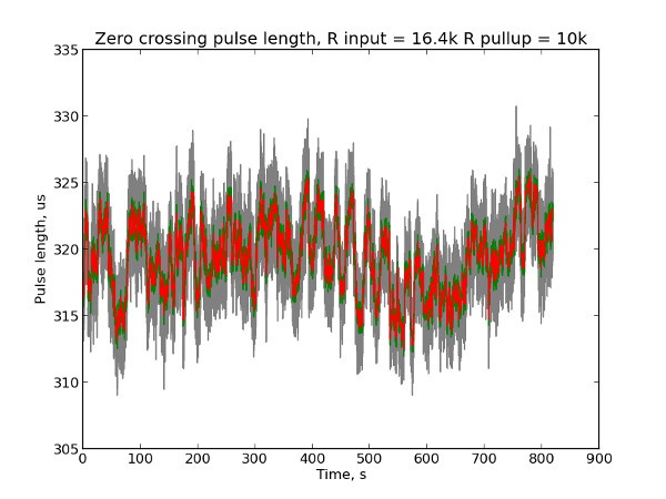
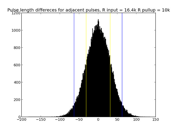
The most of the noise probably could be accounted to the noise present on the AC line - some peaks of the AC sine are higher, then I get narrower pulses, some are lower for wider zc pulses I detect. But hold on. I played a bit with resistor values and plotted this graph, showing distribution of widths of two adjacent pulses.
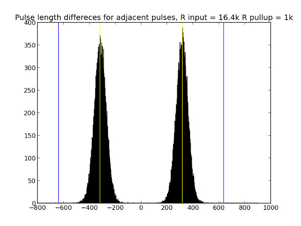
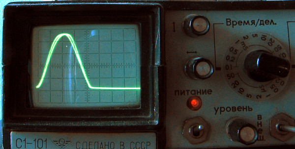
What. A. hell? How come two adjacent pulse lengths are bound to happen in such a uniform manner? While I was posting to the eevblog forum for help, I took a photo of the scope and everything instantly became clear - the two LEDs in the optocoupler ARE NOT IDENTICAL. As you would expect. So I’m really seeing difference in the forward voltage drop of the LEDs. The scope picture shows two superimposed pulses, one for positive half cycle of AC sine, another for - negative.
Well, in general, this was just a scientific detour as errors I get because of this are totally insignificant. I used this knowledge while writing the firmware - I always expect the next ZC pulse to be the same length as the previous one. This way I get 100uS error max, that makes max 1% of total half-period length and cancels the temperature drift of resistors and LEDs.
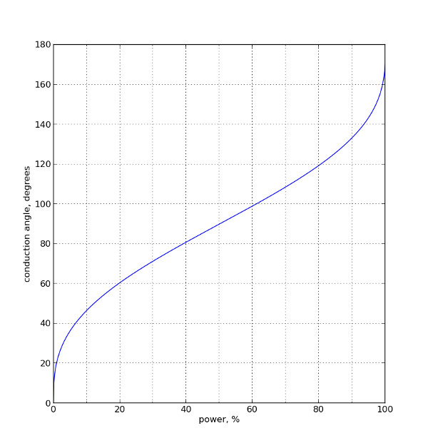
Power output linearization
As AC voltage is sinusoidal and the power in our Universe is proportional to the voltage squared, we are getting the power output to be the integral of the sine squared. Something like this:
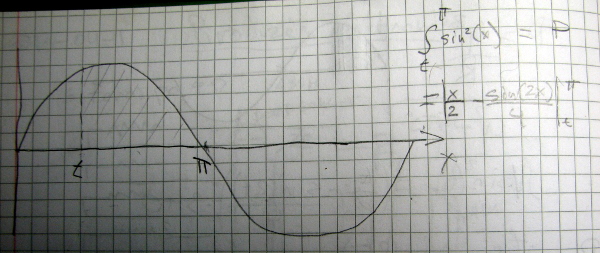
This equation is not easy to solve when you want to get the conduction angle t for desired power P. opit presented great help on this, I’ve used the Newton - Raphson method to solve the equation and to build a table which I’ve used in the firmware:
#solving x - sin(x) = C, f(x) = C - 2x + sin(2x)
#derivative f'(x) = -4sin^2(x)
#x[n+1] = x[n] - f(x[n])/f'(x[n])

import math
import sys
import matplotlib.pyplot as plt
from matplotlib.ticker import MultipleLocator
import numpy as np

def guess(y):
	return y/2;
def fderivative(x):
	return -4 * math.sin(x) * math.sin(x)
def f(x, y):
	return 4 * y - 2 * x + math.sin(2 * x)
def solveIteration(xPrevious, y):
	if 0 == fderivative(xPrevious):
		return xPrevious
	return xPrevious - f(xPrevious, y)/fderivative(xPrevious)
def solve(y):
	x=math.pi/2;#guess(y)
	for i in range(0,100): # 100 iterations proves to be enough
		x = solveIteration(x, y)

	return x

maxConductionAngle = 10000
conductionAngles=range(maxConductionAngle)

for i in range(0,maxConductionAngle):
	conductionAngles[i]=solve(math.pi / 2 / (maxConductionAngle) * i);

xvalues = np.arange(0.0, maxConductionAngle * 1.0, 1)
xvalues = (xvalues/np.max(xvalues))*100

table = np.arange(0, 256, 1)
for i in range(0, 256):
	j = int(i * maxConductionAngle / 255.0)
	print i, j
	if j < 10000:
		table[i] = conductionAngles[j] / math.pi * 10000;
	else:
		table[i] = 10000;

for i in range(0, 256):
	print table[i], ","

conductionAngles = np.array(conductionAngles)

fig=plt.figure()
ax = fig.add_subplot(111)
ax.xaxis.set_minor_locator(MultipleLocator(10))
ax.grid(True, which='both')
plt.plot(xvalues, conductionAngles/math.pi*10000)
plt.ylabel("conduction angle, degrees")
plt.xlabel("power, %")

plt.figure()

plt.plot(range(0, table.shape[0]), table)
plt.show()
We get essentially this graph:
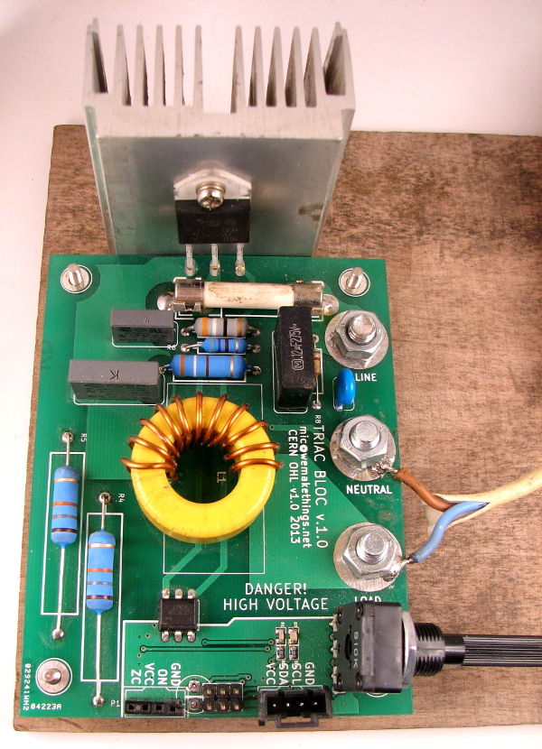
Load testing
I’ve done numerous light dimming tests and one high power test. I’ve hooked up TRIAC BLOC to one heater element of a kiln we will be using for our upcomming pyrolysis project (more on this later some time). The resistance of the cold heating element is 9 Ohms, this in theory should give me 26A of current, in practice I’ve measured 23.8A, that’s 5.7kW. Below you can see my test prototype employing a tiny heatsink for this amount of power. The triac was at 77 degrees Celsius which is probably too high, but I was not able to destroy it. The filter choke was warm to touch, high power tracs too - the fan blowing onto this probably would be totally appropriate. As you can see, I’ve taken advantage of spare MCU pins and hooked up a pot for manual control.