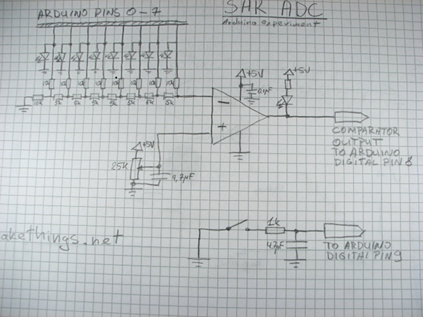
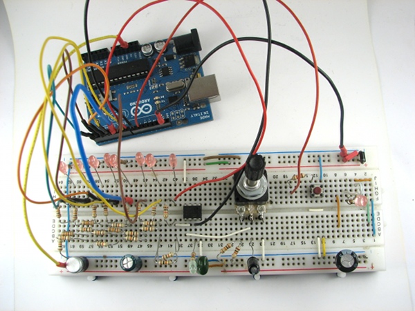
This is a little experiment on how does a SAR ADC work.
A register, a DAC, a comparator and some control logic make an ADC. To perform a conversion, a binary search is performed. Bits in the register are turned on consecutevely from most significant bit to least significant one. If the voltage at the DAC output is higher than the voltage ADC is digitizing, the bit is turned off, if it’s lower, the bit is left on.
What I don’t mention in the video is how accuracy of resistors is important and how different kinds of errors creep in, but it’s a very broad topic on itself. Suffice to say that resistors should be as accurate as possible to get a linear response with low offset and gain errors.
One more thing to mention is that usually there is a so called “sample and hold” capacitor at the “unknown voltage” input of ADC where the voltage is sampled before the conversion so that rapidly changing input does not affect the reading.
This is schematic and Arduino code if someone wants to try it themselves.


#define COMPARATOR 8
#define BUTTON 9

/* button states */
#define PRESSED 1
#define MAYBE_PRESSED 2
#define RELEASED 3
#define MAYBE_RELEASED 4
byte buttonState = RELEASED;
byte lastButtonState = RELEASED;

/* the mask bit we are shifting each step */
byte mask = 0b10000000;

void setup() {
  DDRD = 0xFF; //port D set to output (digital outputs 0 to 7)
  PORTD = 0;   //all bits off
  pinMode(COMPARATOR, INPUT);
  pinMode(BUTTON, INPUT);
  digitalWrite(BUTTON, HIGH); //turn a puu up for a button on
}

void loop() {
  PORTD |= mask; //turn on one bit
  while(!buttonPress()){ //wait for the button press for demo purposes
    //NOTHING
  }
  if(LOW == digitalRead(COMPARATOR)) {
    PORTD &= ~mask; //if comparator turns on, turn off the bit
  }
  mask = mask >> 1; //shift for next bit

  if(0 == mask) {
    while(!buttonPress()){
      //NOTHING
    }
    mask = 0b10000000;
    PORTD = 0;
    while(!buttonPress()){
      //NOTHING
    }
  }
}

/* button debouncing routine */
boolean buttonPress() {
  byte button = digitalRead(BUTTON);
  switch(buttonState) {
    case MAYBE_PRESSED:
      delay(0);
      if(LOW == button) {
        buttonState = PRESSED;
      } else {
        buttonState = RELEASED;
      }
      break;
    case PRESSED:
      if(HIGH == button) {
        buttonState = MAYBE_RELEASED;
      }
      break;
    case MAYBE_RELEASED:
      delay(0);
      if(HIGH == button) {
        buttonState = RELEASED;
      } else {
        buttonState = PRESSED;
      }
      break;
    case RELEASED:
      if(LOW == button) {
        buttonState = MAYBE_PRESSED;
      }
      break;
  }
  boolean ret = lastButtonState != buttonState && PRESSED == buttonState;
  lastButtonState = buttonState;

  return ret;
}