For a long time I wanted to enter the 21st century by stopping using NiCad or NiMH batteries and upgrading to Lithium accumulators as they provide more power per volume and are cool in general. Constant flow of obsolete cell phones provides a nice source of reasonably high-performance batteries for free - I felt compelled to tap into this resource for my battery operated projects.
Well, there are a couple of issues you have to take care of when moving to Li-ion or LiPoly:
- you have to charge them in a particular specific way they like
- you can’t discharge them below a certain threshold
- oh, yeah, did I mention they blow up violently if you screw up?
What’s nice about cell phone batteries is that they usually come with a protection circuitry that protects them when they are overdischarged and short-circuited. Once we tried to blow up a cell phone battery by shorting it, connecting to external power supply in proper polarity, then in reverse polarity, then directly to 240V - the sucker just didn’t blow up! This is just how good protection circuit on cell phone batteries is.
Ok, enough of this retarded shit. I needed a proper way to charge batteries, and I’ve chosen USB from a computer as the primary power source since those are ubiquitous. So, to get the job done I chose to test three (essentially two) popular Li-ion charging ICs: MAX1551, MAX1555 and MCP73831.
There are loads of the charger designs based on these ICs on the net, but I couldn’t find one that would meet my requirements:
- made in Eagle
- DIY toner transfer friendly
- charging/finished indication
- jumper/resistor selectable charging current
- optional USB connector
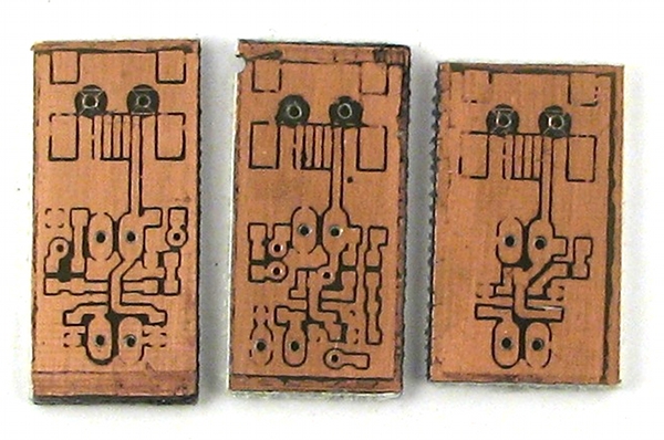
So I made my own and am posting them online for people to use: https://github.com/Miceuz/USBLiPoCharger
MAX1551 does not provide feedback about charging status, so there’s no point talking about it. MAX1555 does provide charging status though, so I took some effort to make use of it:
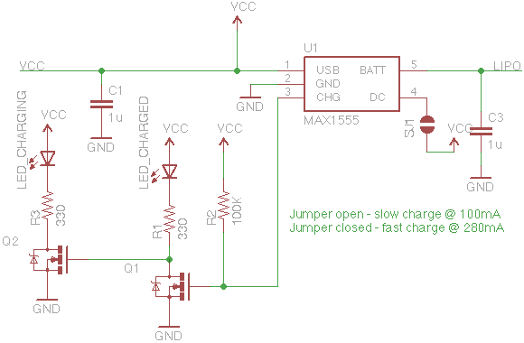
MAX1555 CHG pin is an open drain output that goes low while the battery is charging, stays high impedance otherwise. While the battery is charging, Q1 is off as its gate is pulled low, lucky combination of LEDs and MOSFETs salvaged from some motherboards allows for Q2 to turn on and light up the LED_CHARGING. When the CHG pin goes high impedance, gate of Q1 is pulled up by R2, Q1 turns on while turning on LED_CHARGED and pulling down the gate of Q2.
The MOSFETs I used are of jelly-bean kind with “702” marking on them, the LED_CHARGED has a voltage drop of about 1.6V, this makes a gate voltage of 5V - 1.6V = 3.4V apparently this is enough for 702 to turn on.
I’ve added a solder jumper that can be used to change charging current mode.
MCP73831 has a tri-state STAT output, this makes indication trivial:
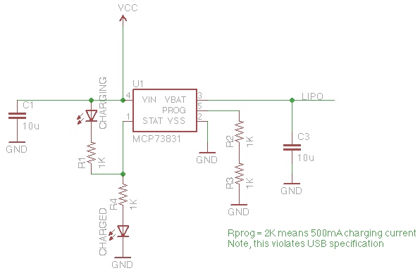
Another nice thing about MCP73831 is that it provides a possibility to tune the charging current for the size of your battery - if the battery is small, you don’t want to charge it at very high currents, probably you’d aim for 0.8 x battery capacity to be on the safe side. This can be done by selecting a suitable resistor on PROG pin - consult the datasheet. Note that you can easily violate the USB specification which does not allow for devices to draw currents higher that 100mA without negotiation. But all the USB hosts in computers I’ve met usually don’t care.
I’m not sure about MAX155X, but I can tell from personal experience that MCP73831 does not have any internal protection form reversed battery. It goes poof! with a tiny trace of smoke.
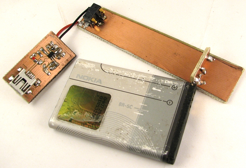
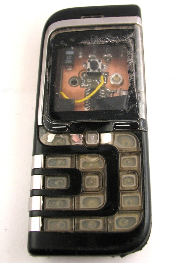
This is a photo of one of my projects - TV-B-Gone packed into a Nokia phone case utilising the original battery:
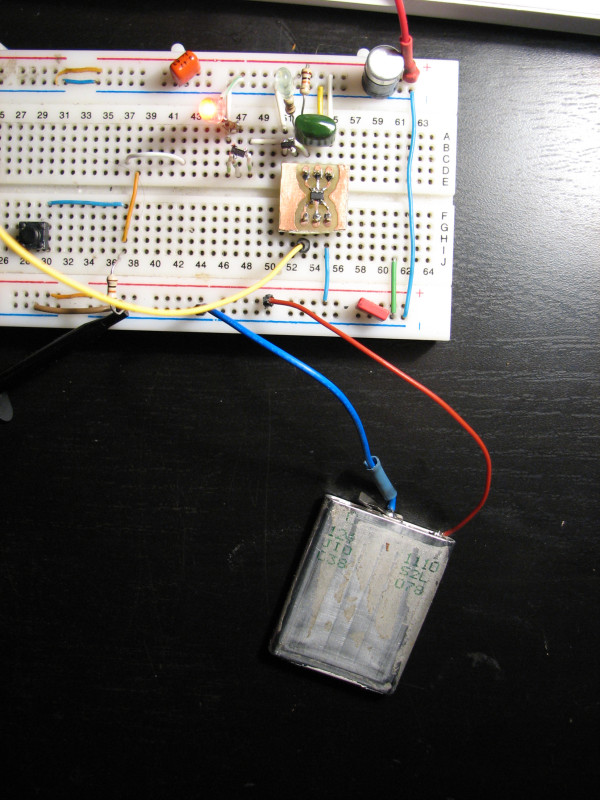
This is a photo of a raw phone battery cell charging. The battery was old and was outputing no voltage, but after I ripped out the protection circuitry, the cell showed some 2.5V - just on the edge of becoming useless. I was able to charge it without any problems - no heating, etc. I don’t recommend this way of using old batteries, it’s here just to show how retarded I am.
