There are two reasons why this contraption came to be.
First, we like coffee. We like a lot of coffee, a lot. Ground coffee from the shop is crap, most of it. Unground beans are twice as expensive. What do you usually do in this case?
You buy it online.
Second, you eventually buy several bags of unground beans, and then realise you have no idea how to roast them.
There are a lot of simple and time-consuming methods. Roasting in a frying pan takes, say, 3 hours of non-stop work to make a kilo of the good stuff. You can’t stick a lot in the oven, too. One could even do it in a popcorn popper or between two meshes.
This last video got me thinking. A cross between that and an industrial drum would be nice. Perhaps a top-loaded washing machine drum, with an electric motor on the side and a gas stove beneath.
Drums and bearings
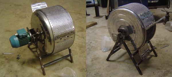
Consequently, I was much pleased when this appeared in the workshop.
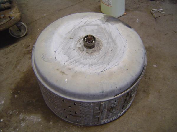
Oh, the things that break and get thrown out!.. My heart sings as I wash them in acid.
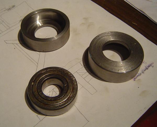
This stainless steel drum has a bearing on either side of the axis. You can see one in the picture above. We got two precision circular mounts for the bearings, made by a professional machinist.
There was also a drawing somewhere on that table, but the whole project went artsy so early on the drawing is not relevant to anything.
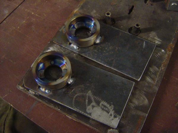
I welded the mounts to strips of 4 mm metal, working it in small increments to prevent warping.
Legs
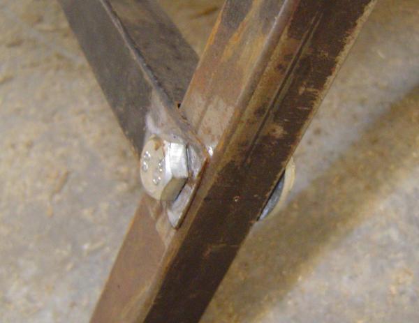
The roaster stands on four legs, two on either side, welded to the metal strips on the outside (so they don’t touch the rotating drum). Square pipe was used here.
Thickness is more or less arbitrary. As to length, I used the diameter of my drum as the dimension. Make it such that the legs and ground form an equilateral triangle. As you remember from school, it is then trivial to calculate their position on the side strips.
Motors
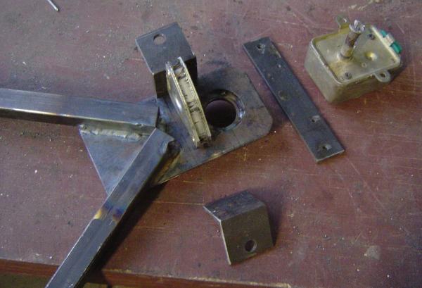
The above image also shows how a motor is to be attached. There are two brackets pointing outwards. A plate of some sort is attached to the motor, and that in turn attaches to the brackets. Why a proxy? Because there’s only so much space. And it’s good to be motor-agnostic in case a motor doesn’t work.
Anyway, the attachment plate has threaded taps to screw the motor on. There are also two threaded taps on the sides of the plate. Their centers are set apart as far as centers of the holes on the brackets. The latter are much bigger (10 mm against 6 mm), so that after the motor is mounted, it can be pushed around a little. This allows centering the motor along the drum’s center axis.
You can see now that our thinking here was quite center-centered. That’s for a reason: a motor will be spinning quite a load here. Speed is negligible enough as far as bearing alignment is concerned, but the motor’s grip alignment isn’t. Besides, it gives an angle at compensating misproper alignment in everything else.
This scheme is implemented on both sides of the drum. They are not identical: there are four brackets on the other side, which allows mounting a much heavier three-phase motor to be controlled with miceuz’ variable frequency drive and a foot pedal.
Of course, only one motor is to be mounted at any given time.
I forgot to take pictures of how the motor actually grips the drum to spin it. Maybe in a follow-up post.
Ribs and assembly
When the leg parts that go on the sides of the drum were all welded together and cooled down, I inserted the bearings and gently tapped them in using a round piece of wood and a hammer. I then assembled them on the drum and measured the distance between the legs on either side.
There were two holes on each leg, drilled prior to all the welding (for ease of manufacture). They are further away from the top end than the radius of the drum.
I measured the distance between the legs on opposite sides of the drum, and cut four pieces of the same square pipe I had. These are for stability, to disallow mischievous acts of falling apart and rolling away.
Accidentally, it allows taking the machine apart, and putting most of it inside the drum, for easy storage and transportation.
Turning beans
You might have also noticed the drum has largish holes along its outer surface. One could weld them over to prevent beans from falling out. But I screwed in some screws instead. They are, of course, stainless steel.
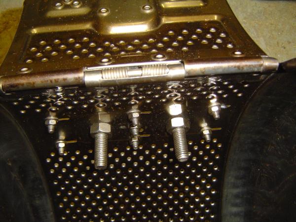
This helps in turning the beans while the drum rotates.
Tests
One thunderous rainy night, as soon as all the chores were done, we decided to have our share of fun and run a few tests.
And I hate to disappoint, but both motors failed and there are no videos of proof.
The smaller motor, 2 RPM, four puny watts of power in a reduction gearbox, failed to lift 1,5 kg of beans. Not enough torque, lever-arm distance too big.
The bigger one, too, couldn’t lift the weight all by itself: it doesn’t have a reduction gearbox, although it does have power (140 W). However, if the drum is first spun by hand, and the motor is then turned on, it picks up momentum and keeps spinning jolly. Except one thing: it spins too fast, like a centrifuge, and all the beans get stuck to the drum’s surface. If there was a burning stove beneath, the beans would get roasted mighty uneven.
Manual override
So I took both motors off, and welded a screw to one side instead, head inwards, and screwed a handle from a meat grinder to it.
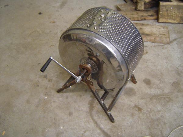
We are yet to test this setup.