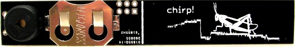
chirp! - the plant watering alarm
What is this?
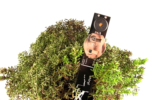
Chirp is a plant watering alarm - as simple as that. You put it into the soil near a plant and it emits a tiny chirp when the soil is dry, reminding you to water the plant. Chirp uses capacitive humidity sensing as opposed to resistive humidity sensing, this means, it does not make an electric contact with the soil, avoiding electrode corrosion and soil electrolysis and resulting in better accuracy and longer battery life.
Special care has been taken not to make it yet another source of annoyance - Chirp will be silent when it’s dark and will restrict itself from making too much noise.
The alarm level can be set for each plant individually. As water is consumed by the plant, Chirp will detect the low moisture level and will start to emit rare short chirps. As more water evaporates, Chirp will increase the alarm rate. Chirp can detect if it’s day or night by measuring the amount of ambient light and will not make noise when it’s dark.
Chirp is Open Source Hardware available under CERN Hardware Licence v.1.1. The device is available for sale directly from the author for 15$.

How to use it?
Chirp was designed to be powered on the smell of a bee’s dick, but alas, bees are hard to catch and contain, so we made it run on a 3V CR2032 lithium coin cell battery. The battery should last up to one year, depending on how good you are on remembering to water your plants. The most energy is consumed when emitting a sound and measuring the light level - this happens when the plant is too dry.
When you insert the battery, Chirp will emit one short chirp, briefly flash the LED and another short chirp after measurement is complete. This means that the device is working properly. It will instantly measure the moisture level on the sensor pad and save it as the “dry point” - the alarm level of moisture.
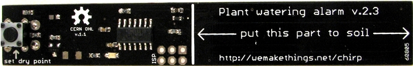
The button on the top side of the device resets the “dry point”. After you press it, the device will emit a short chirp and flash the LED. You can play with it by covering the sensor pad with a wet finger, pushing the button and removing the finger after you hear the second sound. Chirp will think that it is inserted into dry soil and acts as if the plant is too dry.
Installation
To start using Chirp: * Wait until your plant needs to be watered, so you can tell Chirp how much moisture is too little. * Install the battery (watch the polarity!) * Carefully insert the device into the soil up to the line shown on the device. Gently pack the soil around Chirp, so that there are no gaps between the sensor and the soil. * Push the button. Try not to wiggle the device too much while doing that. Do not touch the device, plant or pot for 5 seconds after pushing a button - Chirp needs some time to measure the moisture level undisturbed. * Water the plant. Try not to get too much water on the Chirp.
When the moisture level in the soil drops, Chirp will inform you about that.
If a plant is already too dry and the Chirp is silent, carefully press the button without wiggling the device, wait 5 sec. and water the plant. This way Chirp is set to a new “too dry” level.
If Chirp starts to sound when the plant is still too wet, pull the device out from the soil a little bit - 1cm (1/2 inch), press the button and put Chirp back. Compact the soil around the device.
Totally hackable
I’ve made this device to be hackable and open. It’s based on ATTINY44A microcontroller, the code is available on Github (see below). A standart AVR 6 pin ISP programming header is available on the board for programming and for serial communication.
The device acts as a I2C slave, the header can be used to read the moisture and light levels. Another microcontroller or a board such as Arduino can be used as I2C master to read those levels.
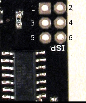
- pin 1 - MISO
- pin 2 - VCC
- pin 3 - SCK / SCL – I2C clock
- pin 4 - MOSI / SDA – I2C data
- pin 5 - RESET
- pin 6 - GND
After reset Chirp reads capacitance and light levels. That can take from 1 up to 9 seconds if dark. If any I2C communication is received during that time, Chirp will switch into sensor mode - it will not chirp, just respond to I2C requests. The default address of the Chirp is 0x20.
Here is some example Arduino code for Chirp:
#include <Wire.h>

void setup() {
  Wire.begin();
  Serial.begin(9600);
}

void writeI2CRegister8bit(int addr, int value) {
  Wire.beginTransmission(addr);
  Wire.write(value);
  Wire.endTransmission();
}

unsigned int readI2CRegister16bit(int addr, int reg) {
  Wire.beginTransmission(addr);
  Wire.write(reg);
  Wire.endTransmission();
  delay(1100);
  Wire.requestFrom(addr, 2);
  unsigned int t = Wire.read() << 8;
  t = t | Wire.read();
  return t;
}

void loop() {
  Serial.print(readI2CRegister16bit(0x20, 0)); //read capacitance register
  writeI2CRegister8bit(0x20, 3); //request light measurement
  delay(9000);                   //this can take a while
  Serial.print(", ");
  Serial.println(readI2CRegister16bit(0x20, 4)); //read light register
  delay(500);
}
Standalone sensor is specifically designed to act as a sensor, thus it can be read faster:
#include <Wire.h>

void writeI2CRegister8bit(int addr, int value) {
  Wire.beginTransmission(addr);
  Wire.write(value);
  Wire.endTransmission();
}

unsigned int readI2CRegister16bit(int addr, int reg) {
  Wire.beginTransmission(addr);
  Wire.write(reg);
  Wire.endTransmission();
  delay(20);
  Wire.requestFrom(addr, 2);
  unsigned int t = Wire.read() << 8;
  t = t | Wire.read();
  return t;
}

void setup() {
  Wire.begin();
  Serial.begin(9600);
  writeI2CRegister8bit(0x20, 6); //reset
}

void loop() {
  Serial.print(readI2CRegister16bit(0x20, 0)); //read capacitance register
  Serial.print(", ");
  Serial.print(readI2CRegister16bit(0x20, 5)); //temperature register
  Serial.print(", ");
  writeI2CRegister8bit(0x20, 3); //request light measurement
  Serial.println(readI2CRegister16bit(0x20, 4)); //read light register
}
Moisture sensing
Chirp uses capacitive sensing to measure the moisture. 1MHz square wave (system clock is used for that) is output from the chip through a resistor into a big pad that together with the surrounding ground plane forms a parasitic capacitor. Resistor and the capacitor form a low pass filter whose cutoff frequency changes with changing capacitance. Soil around the sensor acts as an electrolyte whose dialectric constant changes depending on the amount of moisture in it, so the capacitance of our makeshift capacitor changes too. The filtered square wave is fed into a peak detector formed of out a diode and a capacitor - the diode lets through positive peaks and the capacitor stores the maximum voltage of those peaks. This voltage is measured by an ADC in the microcontroller. I wrote a long writeup on this technique some time ago.
Light sensing
A simple LED is used as a light sensor. Capacitive properties of diodes are used. LED is driven forward-biased for some time, then it’s driven reverse-biased to charge the internal capacitance. The time it takes for this internal diode capacitance to discharge depends on the amount of light that falls into the diode. Microcontroller timer is used to measure this time and estimate how much ambient light is out there.
Open source
Chirp is Open Source Hardware available under CERN Open Hardware Licence v.1.1.
All the schematics and code is available at https://github.com/Miceuz/PlantWateringAlarm.
History
Chirp started as a joke - I was sure I will forget to water the plants, so I have put togeather a simple opamp - based prototype that worked OK, but was not practical. After that I’ve tasked myself to create a low power design based on capacitive sensing idea.
At first I went a straight forward path - just charge the capacitance and count the time it takes for it to discharge. This aproach works for building capacitor meters, but has a significant drawback - in order to gain reasonable resolution, I had to run the microcontroller on high frequency and use a fairly big resistor while discharging the sensor capacitance. This high value resistor is a problem as the sensor track acts as a fairly good antenna and is eager to pick up any noise that’s out there.
Then I went for approach that is used in the current design - filter the square wave and half rectify it to get estimate of capacitance. This approach lets me use much lower resistance (10k instead of 510k) and get rid of noise problems.
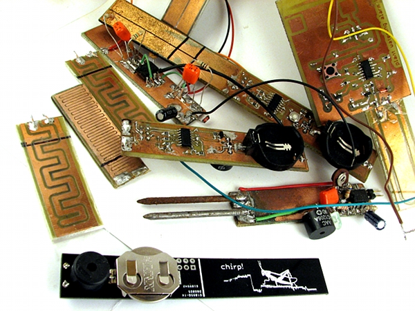
Then there was a question - what shape of track will give me the most dynamic range? I’ve solved this expermentaly, by making several sensor pads and testing them separately.
…and a bunch of prototypes later this is what we have…
Contact
If for whatever reason you want to contact me, you can write me to mic at wemakethings.net or follow me on twitter twitter.com/miceuz