I’ve spent some time playing around the idea of using stepper or brushless motors as rotary encoders.
Stepper acts as a high impedance AC voltage source outputing sinusoidal waveform, it’s just a matter of apmlifying and converting this signal to a square wave:
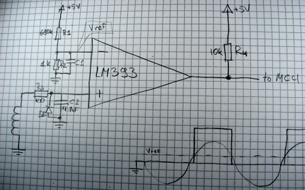
R1 and R2 set up a reference voltage, R3 and C2 low-pass filter the signal from a motor - when this signal goes above the reference voltage, comparator changes it’s output producing a nice square wave.
The same effect can be obtained using a high gain noninverting op amp circuit, but as opamps are not really ment to be operated in saturation regions, I’ve decided to go with a comparator.
You have to do this to two phases of a stepper motor - one phase will lag the other - this way you can determine a direction of rotation.
Here is a piece of arduinized avr code that reads the encoder and drives a single digit 7 segment display:
void setup() {
  DDRD = 0xFF;//setup port D as ouput for 7-seg display
  pinMode(8, INPUT);//motor phase 1 on PORTC 0
  pinMode(9, INPUT);//motor phase 2 on PORTC 1
}


byte digits[] = {
  0b00000011,//0
  0b11110011,//1
  0b10000101,//2
  0b00001101,//3
  0b00111001,//4
  0b01001001,//5
  0b01000001,//6
  0b00011111,//7
  0b00000001,//8
  0b00001001,//9
};

byte t = 0; //step counter
byte lastVal = 0; //last value of motor phase inputs
byte b = 1; //segment which is displayed
byte digit = 0; //digit that is displayed

void loop() {
  //flash one segment every loop
  PORTD = digits[digit] | ~(0x01 << b);
  b++;
  if(b > 7) {
    b = 1;
  }

  //read status of motor pins
  byte val = PINB & 0x03;

  if(val != lastVal) {
    if((val == 3 && lastVal == 2) ) {
      //t is just a step counter, we change the digit every 3 steps
      t++;
      if(4 == t) {
        t = 0;
        digit++;
        if(10 == digit) {
          digit = 0;
        }
      }
    } else if ((val == 2 && lastVal == 3) ) {
        if(0 == t) {
          t = 4;
          if(0 == digit) {
            digit = 10;
          }
          digit --;
        }
        t--;
    }
    lastVal = val;
  }
}