It’s an electronics part of merry-go-round saga. Read the first part about mechanics before.
The task
When pwf asked me if I’d like to put some thought into this merry-go-round affair they were going to pull of, I didn’t hesitate much - the project was a good test of my electronics skills and my niggaz needed me - how could I refuse?
The task at hand was like this - the carousel hangs from a ceiling, it is driven by a variable frequency drive, there is a stage wheel beneath it which rotates, the carousel has to rotate together with the stage wheel in one mode and has to rotate fast (how fast is too fast?) in the other mode.
At first we were going to take readings from the shaft of the motor that drives the stage wheel (i’d even quickly made a tachometer from parts from a junk bin), but after inspection of all the mechanisms we understood that there was no chance - the age of the system approaches the years when people were walking on the Moon and it hasn’t seen much love from any caring engineer during all this time.
We decided to take the readings by attaching a rubber wheel with a rotary encoder to the steel bottom rim of the stage wheel - this way we could be sure that we get the exact measurements of movement of the edge of the stage wheel.
What about the carousel? We’ve chosen a variable frequency drive with a modbus option, so we could control it remotely, but what about the feedback? Luckily it came to me early enough in the process: we need a closed loop system for synchronization to work properly. It might have worked in the open loop mode, but the system was unknown, there was no time for testing, so when in doubt - overengineer - we’ll have another rotary encoder that’s reading the rotation of the carousel. This way we have a PID system that ensures that both the stage wheel and carousel have rotated exactly the same amount. Provided encoder readings correspond to a real rotation. Read on.
Reading encoders
Ok, how do you transfer pulses from the encoder that might be up to 100m from the control panel? When in doubt… I’ve decided to use RS485 as a wire protocol for that. Quickly enough nice folks from Linear Technology and Maxim-ic have provided me with free engineering samples of receivers, drivers and transceivers. Far quicker than buying from distributors. And free.
We used a high-end encoder from precizika. Conveniently it was outputting a differential signal, so I’ve used MAX3095 to read it and LTC486 to transmit it down the line.
I had time to take some nice pictures:
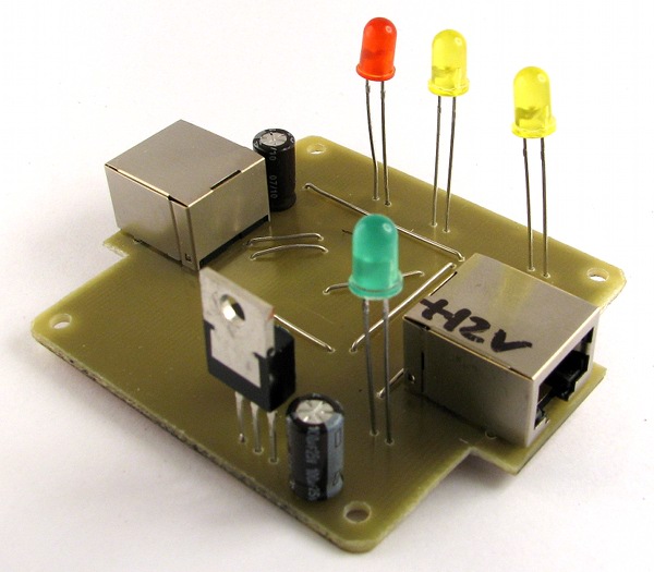
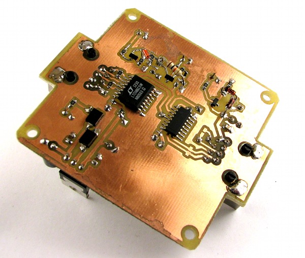
But that’s boring. The fun part was designing all the protection - the thing was meant to be used in a theatre and things do get messed up in a theatre. The adapter uses the same RJ45 connectors for input and output, I know it’s a BAD THING(tm), but those connectors were too convenient to not to use them, so I’ve had a nice afternoon designing a foolproof protection from reverse connections. And a fault indication.
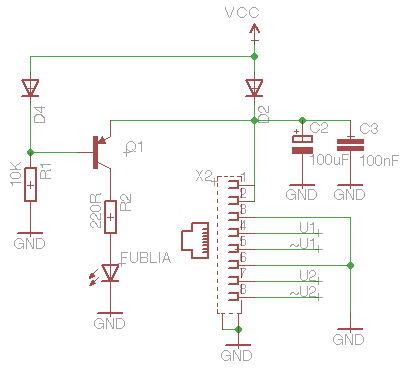 It’s an encoder-side connector that usually outputs voltage. If the system sees voltage on 1 and 2 pins (this happens if you reverse connectors), the FUBLIA LED lights up and bad things do not happen.
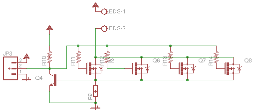
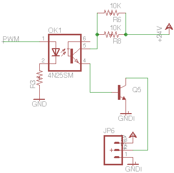
Another fun part was developing an edge detector to blink some LEDs when pulses from the encoder are coming:
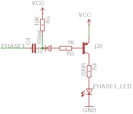 Note the extensive use of PNP transistors - I have a pile of them left after a project before, had to use ‘em up!
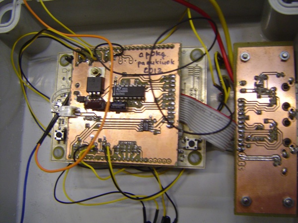
Control unit
The control part is really boring, it’s just my CatNip board with a special ‘kitteh’ - a ‘shield’ to condition RS485 signals, read some buttons and blink some LEDs. I’ve used LTC488 receiver to match the Linear Technology driver on the encoder adapter and LTC485 to talk to the variable frequency drive. I’ve written a of couple semi decent modbus functions. The whole code is at my github repo.
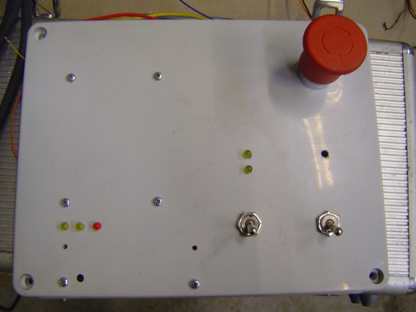
This is a picture of our control panel:
Well, all of this was a “clean room” design exercise - as the guys in the workshop were cutting and welding steel like real men, I had to emulate the unknown parts of the system. When I came to the workshop, the carousel was in rather early stages of being complete, so I had to spend some time writing utilities to graph step response, read on control systems theory and design a DMX LED dimmer while eating spacecake. I didn’t have an opportunity to run my system until the carousel, still hot from welding, was brought and installed in the destination place.
The Motorized Plow
That’s where the fun started. My system worked quite well, but there was a problem with a stage wheel - the steel rim we were running our encoder wheel on was not that round after all. One fourth of the circle was squashed inside, so the carousel would go with the stage within the error of 10cm for 3/4 of the circle and run away in the last quarter. I could have thought of some trick in software, but because of sleep deprivation my skull was full of scrambled eggs instead of brains. So either you solve optic problems with optics, mechanical with mechanics and electrical with electronics or you solve all the problems in software. This time we went the former way - pwf added one more degree of freedom to the encoder wheel fixture, changed its angle and orientation on the rim and we were able to follow the wheel for two to three rotations within allowance of 20cm. Which was totally OK for our purposes, but it left a bad taste in my mouth. Check out the first part for the crappy video of synchronization in action.
When I got up in the theatre (I’ve slept there, because I was too exhausted to go home), I was greeted by a flock of 50-year old males in formal suits - the theatre management. They brought an old man with them, who still works there as an electrician, but probably still remembers the times when men were walking on the Moon. This old man started telling me story about how he managed to build himself a motorized plow for his garden out of ropes and pulleys. Aha! That’s why stage wheel is in such a sorry state…
There is some pr0n to look at in the meantime:
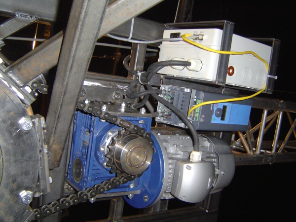
Here you can see an AC induction motor, variable frequency drive for it, a reduction box with a chain to drive the carousel and a box that will hold electronics for a DMX LED dimmer.
DMX LED dimmer
How long does it take to design and make a fully functional DMX LED dimmer? Two nights while eating spacecake to draw a PCB, one day to get the parts, etch and solder the boards and one day and one night to write firmware, test and install it.
As an optional bonus there had to be LED strips on the carousel, controllable via DMX. Well, how do you transfer power to a rotating thing? Ground goes through the frame, and live wire goes through a graphite brush on a slip ring. How much resistance/voltage drop do you get when the carousel rotates? Unknown. When in doubt… overengineer! We got this beefy transformer out of a trashed guitar amplifier, it was outputting 30V. And we hooked up a constant current source that would compensate for the voltage drop through the slip ring and bearings. And we made a nice 50W heater out of 4 parallel MOSFETs and a huge heatsink. But what if one of several LED strips is not connected? You get the same current pushed through the remaining ones of course. Hm.. no good, let’s put a PTC on every LED strip.
This is a constant current source:
As for DMX part - it’s nothing fancy - just an AVR atmega8 hooked up via MAX3095 to DMX line via an optocoupled open collector output to pull the gates of MOSFETs down via PWM.
I used some rxdtxd’s DMX decoding code. The whole thing is on github if someone is interested: https://github.com/Miceuz/DmxLedDimmerBasic
PTC’s on the strips paid off nicely as one of those crap Chinese strips was shorting to the frame! Now just imagine all the things we said after discovering this at 5 o’clock in the morning!
Aftermath
Well, it was a nice hell of a deathmarch involving a bunch of people, using a load of different skills and techniques. There was too much of things we didn’t know beforehand and no time to test ideas. Nevertheless, we are very lucky to have pulled this off. When in doubt… overengineer!